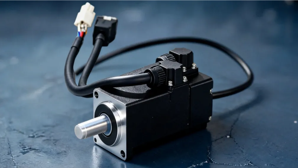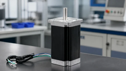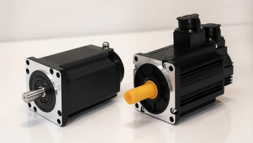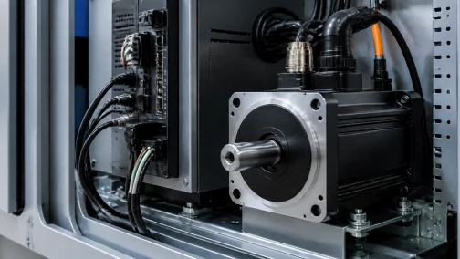

Correct Wiring Determines Driver Compatibility and Motor Performance
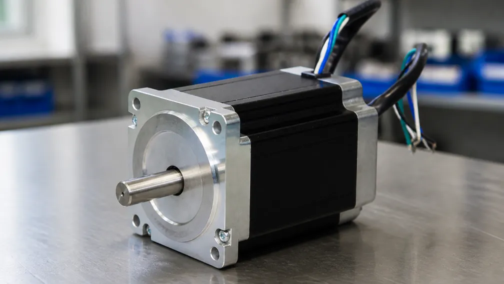
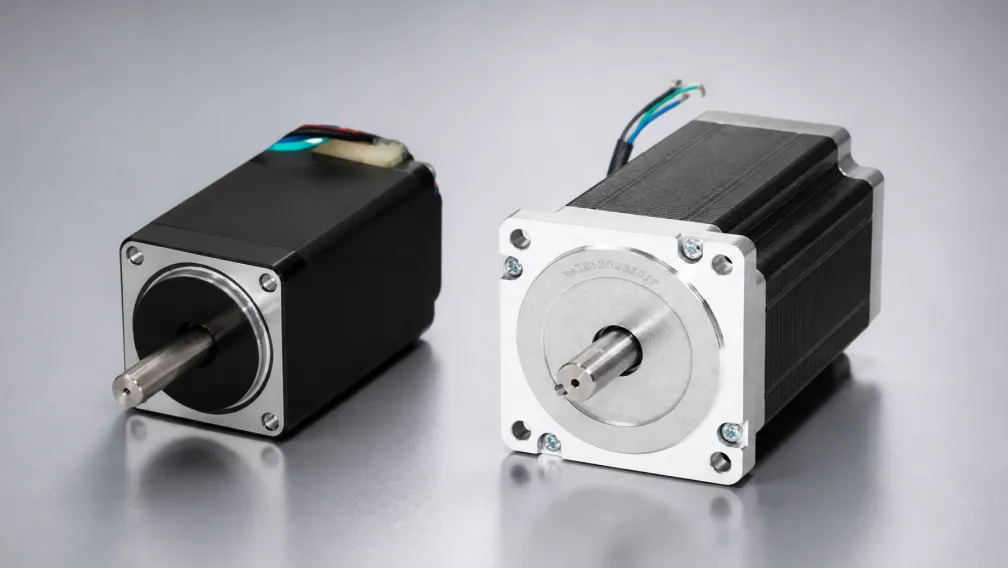
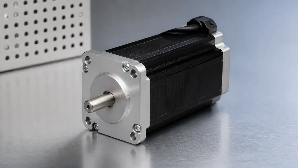
Stepper motor wiring defines how the driver energizes each phase. It also determines the applicable phase-current rating, winding resistance, inductance, torque behavior, and maximum usable speed. A motor that vibrates without turning, runs hot, or loses torque at speed is often wired incorrectly or configured with the wrong connection-specific current value.
For industrial equipment, wiring should be treated as an engineering specification. The bill of materials should identify the motor's lead count, winding diagram, phase assignment, connector pinout, cable length, and current rating for the selected connection. Lead color alone is not a reliable specification because color codes vary between manufacturers.
1. Identify the Winding Before Connecting the Driver
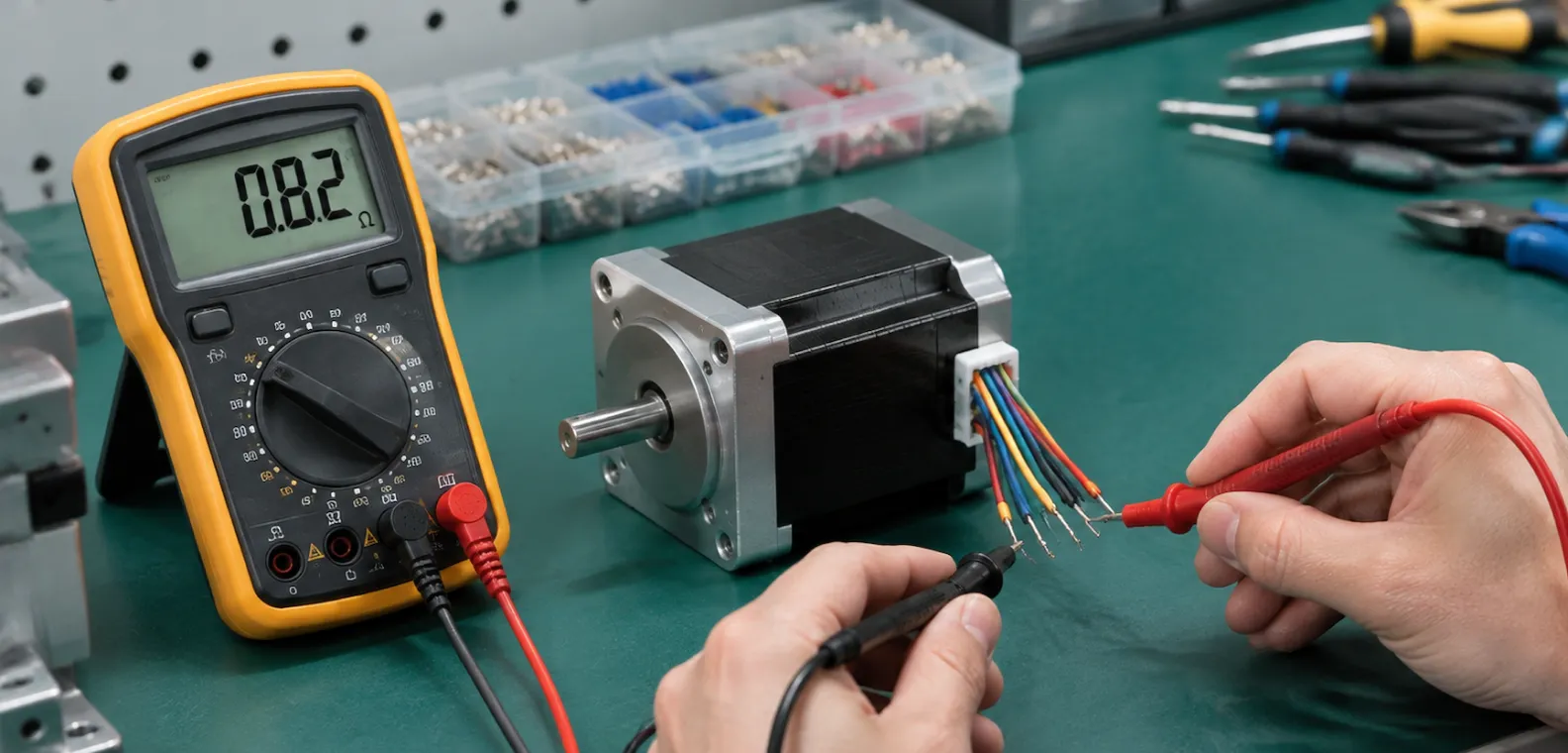
The first source is the motor datasheet. A usable datasheet should show the internal coil arrangement, lead colors or terminal numbers, phase polarity, and connection-specific ratings. If the datasheet is unavailable, a digital multimeter can identify coil groups with the motor disconnected from power.
Use this identification sequence:
- Disconnect the motor from the driver and allow the DC bus to discharge.
- Measure resistance between each pair of leads and record the values.
- Group leads that show continuity. Open-circuit readings indicate separate windings.
- For center-tapped windings, compare resistance from the suspected center tap to each end. The end-to-end resistance is approximately twice the center-to-end value.
- Confirm that no winding is shorted to the motor frame.
- Connect the identified phases to the driver according to the wiring diagram, then test at reduced current and low speed.
A resistance measurement identifies winding groups. It does not establish a safe operating current. Phase current must come from the manufacturer's rating or a validated motor-driver set.
2. Lead Count and Driver Compatibility
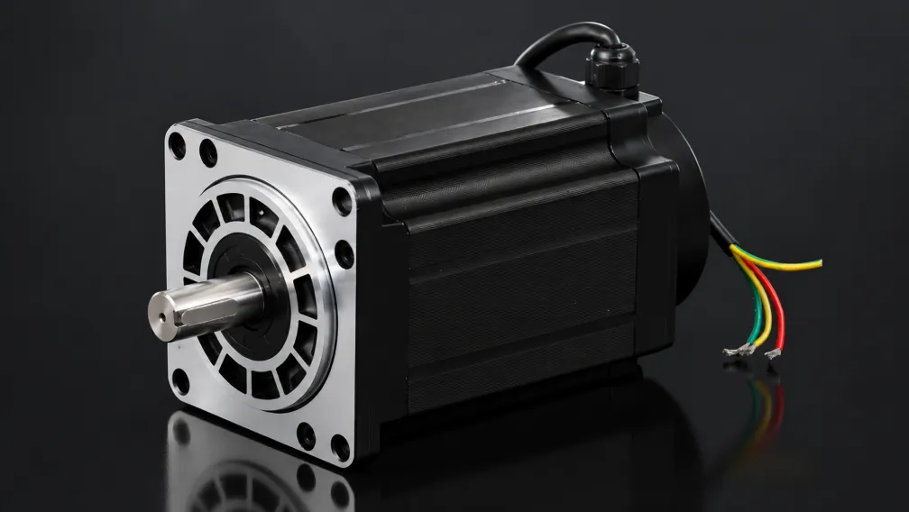
Lead count indicates how the winding sections are brought out of the motor. It also defines which driver topology can be used.
| Lead Count | Internal Arrangement | Compatible Drive Method | Engineering Notes |
|---|---|---|---|
| 4 wires | Two isolated phase windings | Bipolar chopper driver | Standard choice for modern industrial stepper systems |
| 5 wires | Two center-tapped windings with common connection | Unipolar driver | Not suitable for a standard bipolar H-bridge driver |
| 6 wires | Two center-tapped windings with separate taps | Unipolar driver or bipolar driver | Bipolar operation uses the full coil or half coil |
| 8 wires | Four accessible winding sections | Unipolar or bipolar driver | Supports series, parallel, and half-coil configurations |
A standard 2-phase stepper motor for industrial positioning commonly uses a 4-wire bipolar winding or an 8-wire configurable winding. The matching motor driver must be selected for the chosen connection.
3. Four-Wire Bipolar Wiring
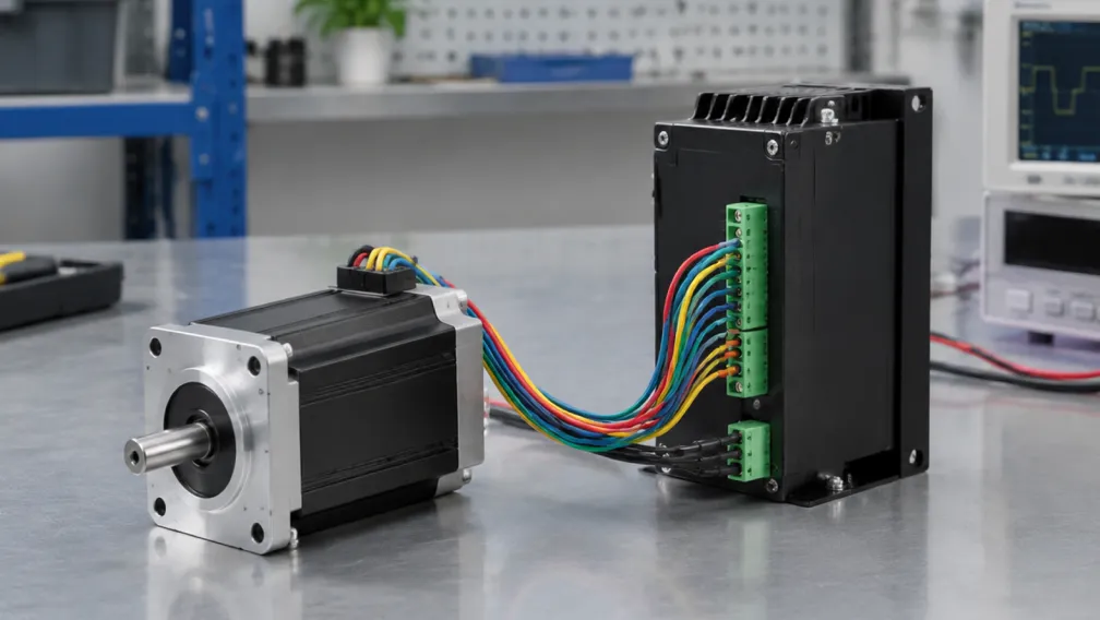
A 4-wire motor contains Phase A and Phase B. Each phase has two leads. The driver terminals are normally marked A+, A-, B+, and B-. The wiring task is to place each identified coil on the correct phase output.
Once the two phase pairs are identified, connect one pair to A+/A- and the other pair to B+/B-. If the shaft turns opposite to the commanded direction, use the controller's direction setting or reverse one complete phase pair according to the driver manual. Do not move wires while the driver is powered.
This arrangement gives the driver access to the full winding and supports current-regulated microstepping. It is the preferred configuration for compact NEMA 17, NEMA 23, and larger positioning axes when the driver provides the required current and voltage range.
4. Six-Wire Center-Tapped Wiring
A 6-wire motor has two windings, each with two end leads and one center tap. The center taps support unipolar operation because current can be driven through half of each winding in one direction.
For unipolar use, the center taps connect to the driver's common supply terminals and the four winding ends connect to the switching outputs. This method uses simpler drive electronics, although only half of each winding carries current at a time.
A bipolar chopper driver can also operate many 6-wire motors using one of two methods:
- Full-coil bipolar: Connect the two end leads of each phase and leave both center taps insulated and unconnected.
- Half-coil bipolar: Connect one end lead and the center tap from each phase, leaving the other end leads insulated and unconnected.
The current rating changes with the selected connection. A value listed for unipolar operation should not be transferred directly to full-coil or half-coil bipolar operation unless the manufacturer states that the rating is valid for that configuration.
5. Eight-Wire Series, Parallel, and Half-Coil Wiring
An 8-wire motor separates each phase into two winding sections. This allows the motor to be adapted to the available driver voltage and current. The winding diagram must be followed exactly because a wrong cross-connection can short the driver output or oppose the magnetic fields.
Bipolar Series Connection
Series wiring connects the two sections of each phase end-to-end. It uses the full winding and produces strong low-speed torque with a lower current setting. The tradeoff is higher resistance and inductance, which reduces the driver's ability to maintain current at high speed.
Use series wiring when the application prioritizes holding torque, low-speed stiffness, or a lower-current driver. It is common on heavier positioning axes where maximum speed is limited.
Bipolar Parallel Connection
Parallel wiring connects the two sections of each phase in parallel. This reduces resistance and improves current rise at speed. It requires a higher phase-current setting and a driver with sufficient output capacity.
Use parallel wiring when the axis needs stronger high-speed torque or faster acceleration. Confirm the driver, power supply, cable gauge, and connector rating for the higher current before energizing the axis.
Half-Coil Connection
Half-coil wiring uses one winding section from each phase. It offers lower inductance than full-coil series wiring, which can help at higher step rates. Available torque is lower because the full winding is not used.
Connection Selection Summary
| 8-Wire Configuration | Current Requirement | Torque Behavior | Speed Behavior | Typical Use |
|---|---|---|---|---|
| Bipolar series | Lower | Strong at low speed | Torque falls earlier as speed rises | Low-speed, high-holding-torque axes |
| Bipolar parallel | Higher | Strong low-speed torque | Better high-speed current rise | Fast indexing and higher-RPM automation |
| Half-coil | Connection-specific | Reduced torque | Useful when lower inductance is required | Specialized speed-focused setups |
Series, parallel, and half-coil values are connection-specific engineering ratings. The selected connection must appear in the motor specification, driver setting, inspection record, and service documentation.
6. Match the Driver Current to the Selected Wiring
The driver current limit should be set only after the wiring method is fixed. A motor datasheet may list different phase-current values for unipolar, series, parallel, and half-coil operation. Applying a parallel-current value to a series connection can overheat the motor. Applying a series-current value to a parallel connection can reduce available torque.
Check these items together:
- Motor wiring configuration and phase-current rating
- Driver adjustable current range and RMS/peak convention
- Supply voltage and driver input limits
- Cable gauge, connector current rating, and ambient temperature
- Required torque at the operating speed
- Motor case temperature after the longest duty cycle
When a motor and driver are supplied as a matched set, the connection and current setting should be documented before shipment. This removes a common commissioning error and gives the equipment builder a known electrical baseline.
7. Encoder and Closed-Loop Wiring Requirements
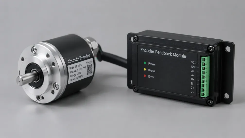
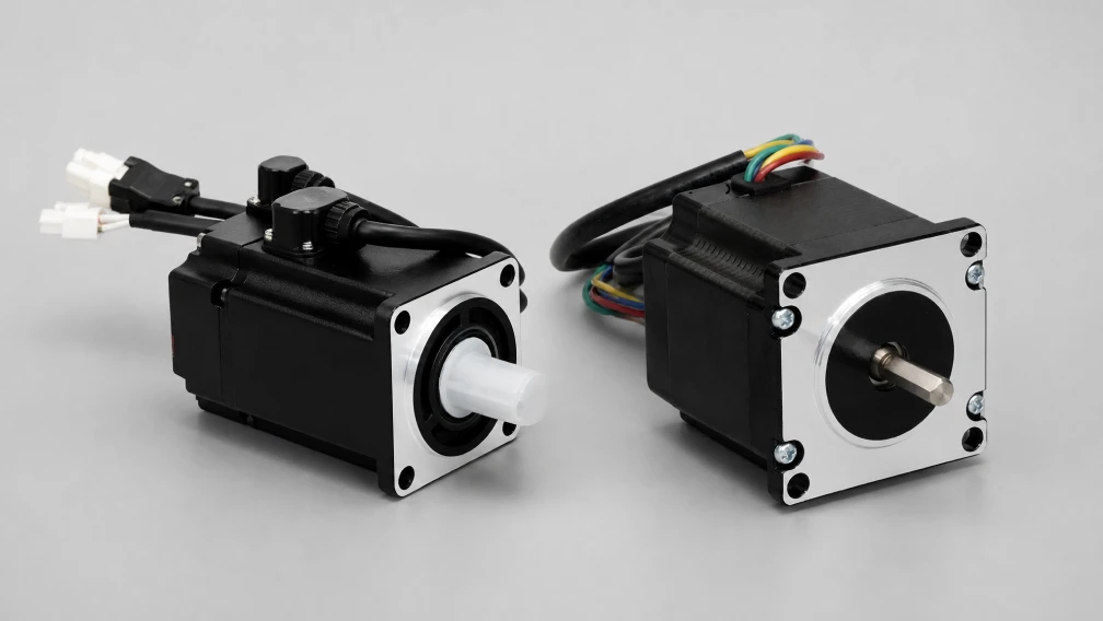
A closed loop stepper motor adds encoder feedback to the motor phase wiring. The encoder cable carries low-voltage signals and must remain separate from the high-current motor phase leads unless the cable assembly has been designed and tested as one shielded harness.
Use the encoder pinout supplied with the motor. Confirm A/B/Z signal polarity, supply voltage, grounding, and shield termination at the driver. Do not connect encoder leads to motor phase terminals. A phase wiring error can cause rough motion or no motion; an encoder wiring error can cause following-error alarms, uncontrolled correction, or immediate driver faults.
8. Cable, Connector, Grounding, and EMI Practice
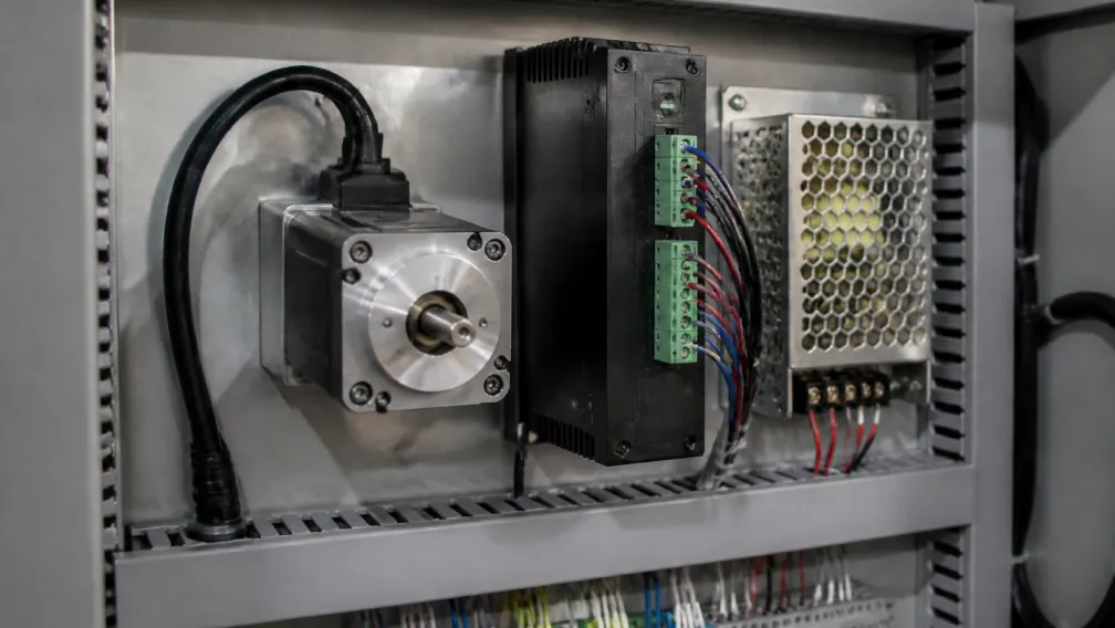
Motor phase cables should use conductors sized for the configured current and cabinet temperature. Twisted phase pairs reduce loop area. Encoder and communication cables should be shielded and routed away from motor power cables where possible. Cross power and signal cables at right angles when separation is limited.
Connect the motor frame, driver protective earth, and supply ground according to the equipment standard. Keep phase-lead joints inside rated connectors or terminal blocks. Avoid solder-only splices in high-vibration equipment. Use strain relief so cable movement does not load the terminal.
Before energizing a new axis, check continuity, phase grouping, insulation to frame, terminal torque, connector retention, and cable routing. During commissioning, never connect or disconnect a motor phase while the driver is powered.
9. OEM Specification Checklist
A procurement-ready motor wiring specification should include:
- Lead count and winding diagram
- Phase assignment and polarity convention
- Connection-specific current, resistance, and inductance
- Lead wire gauge, insulation rating, and length
- Connector model, pinout, crimp specification, and locking method
- Encoder pinout and shielding requirement when feedback is installed
- Label format and traceability requirement
- Driver model, current setting, and supply voltage
Cymotorix supports custom winding, lead length, connector, encoder, gearbox, and brake options across its stepper motor range. For a wiring review, send the motor drawing, driver model, selected connection, current setting, cable length, and target operating speed through the application engineering contact page. Datasheets and dimensional drawings are available from the download center.
Frequently Asked Questions (FAQ)
Question: Can a 6-wire stepper motor be used with a bipolar driver?
Answer: Yes, many 6-wire motors can operate in full-coil bipolar mode by using the two end leads of each phase and insulating the center taps. Some motors also support half-coil bipolar operation. Use the connection-specific current rating from the manufacturer.
Question: What is the difference between 8-wire series and parallel wiring?
Answer: Series wiring uses the full winding with lower current and higher inductance, supporting strong low-speed torque. Parallel wiring lowers resistance and improves current rise at speed, but requires a higher driver-current setting and a suitable power supply.
Question: Can I use the same driver current for every wiring configuration?
Answer: No. Series, parallel, half-coil, and unipolar connections can have different allowable phase currents. Set the driver only after the connection is selected and confirmed against the motor datasheet.
Question: Why does the motor vibrate without turning after wiring?
Answer: Common causes include incorrect phase pairing, one open winding, a loose connector, wrong pulse timing, insufficient current, or a mechanical bind. Disconnect power before checking wiring, then verify phase continuity and driver settings.
Question: Are stepper motor wire colors universal?
Answer: No. Lead colors vary between manufacturers and product series. Use the wiring diagram or multimeter identification. Do not copy a color code from another motor without confirming the pinout.
Question: Will reversing two wires change motor direction?
Answer: Reversing one complete phase pair can change the effective rotation relationship, but the preferred method is to change the controller's direction parameter or DIR signal logic. Follow the driver manual and power down before changing wiring.
Question: Can encoder wires and motor phase wires share the same cable?
Answer: They should remain separate unless the complete cable assembly is shielded, rated, and tested for that motor-driver set. Encoder signals are low-voltage feedback lines and can be disrupted by high-current motor switching.
-

Cymotorix
Stepper Motor & Servo Motor Manufacture
Cymotorix is a China-based motor manufacturer with 20+ years of experience producing hybrid stepper motors, AC servo motors, and matched drivers for OEM customers worldwide.