
The Mechanical Necessity of Positional Feedback
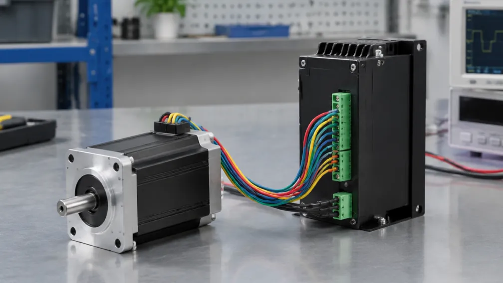
The fundamental limitation of open-loop actuation is the lack of physical verification. A machine controller issues a pulse train and assumes the motor executes the exact physical movement. If the payload encounters unexpected mechanical resistance, the rotor stalls while the controller continues indexing the internal coordinate. This tracking divergence ruins machined workpieces and crashes mechanical gantries. Integrating a feedback device transforms the motor into a closed-loop platform. The encoder is the sensory organ of this system, providing real-time positional data to the drive's Field-Oriented Control (FOC) algorithms.
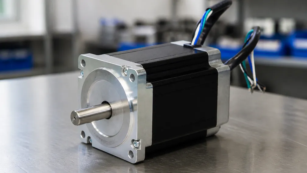
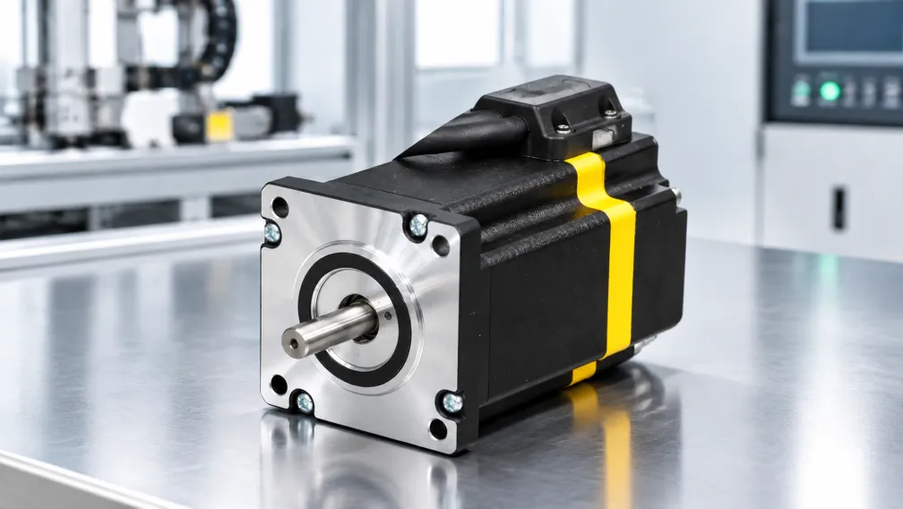
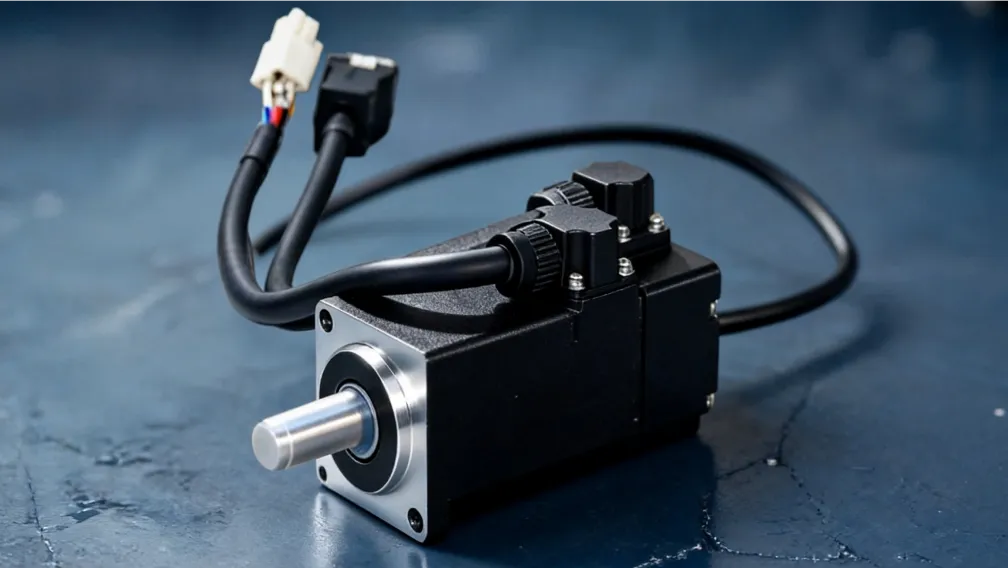
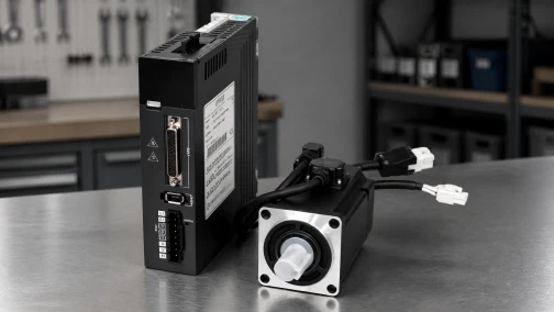
The physical architecture of this feedback device—whether optical or magnetic, incremental or absolute—dictates the maximum operating temperature, vibration tolerance, and velocity loop stability of the entire automation axis. Specifying a high-end servo motors platform with an inappropriate encoder technology leads to jitter, signal loss, and premature hardware failure. This technical manual evaluates the operational physics of industrial encoders, compares optical and magnetic sensing arrays, and defines the engineering metrics for specifying feedback components in motion control systems.
1. Optical Encoders: Mechanics and High-Precision Linearity
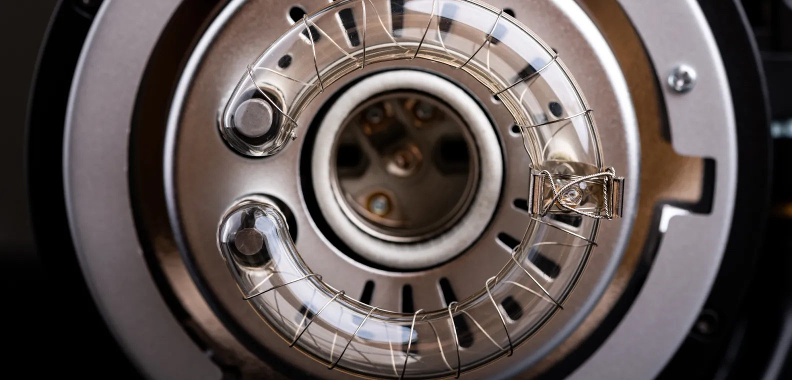
Optical encoders are the historical standard for precision motion control. The internal mechanism consists of an LED light source, a rotating code wheel (disk), and a stationary photodetector array. The rotating disk is typically manufactured from etched glass, metal, or Mylar film, featuring microscopic transparent and opaque radial lines. As the motor shaft rotates, the lines interrupt the light beam, causing the photodetector to generate distinct electrical pulses.
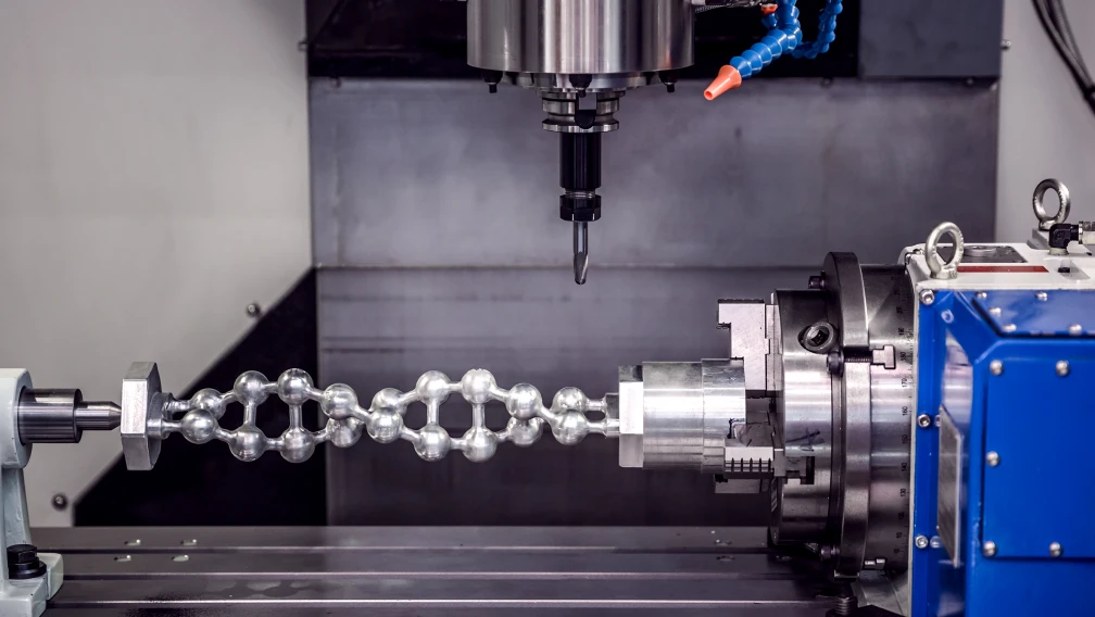
The primary advantage of optical technology is its extreme linearity and absolute immunity to external magnetic fields. The precision of the photolithography process used to etch the glass disks allows for native resolutions exceeding 10,000 pulses per revolution (PPR) without requiring aggressive electronic interpolation. Optical encoders deliver the highly accurate, low-jitter signals required for CNC machining centers, laser cutting heads, and semiconductor wafer handling.
However, the optical architecture possesses strict environmental limitations. The clearance between the rotating disk and the photodetector is microscopic. If condensation forms inside the housing, or if fine particulate dust penetrates the seal, the light beam is refracted or blocked, causing immediate signal failure. Furthermore, glass disks are susceptible to shattering under severe mechanical shock or continuous high-amplitude vibration.
2. Magnetic Encoders: Durability in Harsh Environments
Magnetic encoders operate entirely on solid-state electromagnetic physics, eliminating the fragile optical disk. The architecture consists of a diametrically magnetized permanent magnet mounted directly to the motor shaft, rotating above an integrated circuit containing Hall-effect sensors or magnetoresistive elements. As the magnet rotates, the sensor array measures the changing flux angle and converts the magnetic field vector into digital positional data.
Because magnetic encoders do not rely on a line of sight, they are entirely impervious to dust, oil, condensation, and airborne particulates. The sensor and the rotating magnet can be encapsulated in potting compound, allowing the assembly to achieve IP67 or IP69K ingress protection ratings easily. The lack of a glass disk also renders them highly resistant to mechanical shock and vibration, making them the standard choice for automated guided vehicles (AGVs), heavy agricultural automation, and industrial washdown environments.
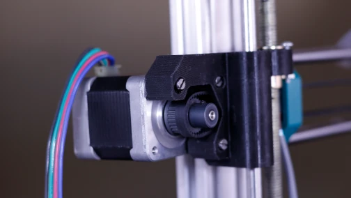
The historical trade-off for magnetic durability was lower resolution and positional latency. Early magnetic encoders suffered from hysteresis and nonlinearity at the pole boundaries. However, modern interpolator chips now synthesize the raw magnetic sine/cosine waves into ultra-high-resolution signals, allowing magnetic encoders on closed loop stepper motors to rival standard optical units in general automation tasks.
3. Incremental vs. Absolute Feedback Architectures
Beyond the sensing medium (optical vs. magnetic), engineers must specify how the positional data is formatted and transmitted to the driver.
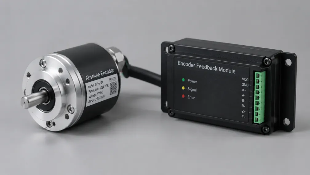
Incremental Encoders: An incremental encoder generates relative position data. It typically outputs two square wave channels (Channel A and Channel B) offset by 90 electrical degrees (quadrature). The driver counts these pulses to track distance and determines direction based on which channel leads the other. The critical limitation of an incremental system is volatility: when power is removed, the current physical position is lost. Upon power-up, the machine must execute a slow "homing" routine, moving the axis until it triggers a physical limit switch to re-establish its zero coordinate.
Absolute Encoders: An absolute encoder assigns a unique digital code (often Gray code) to every specific angular position of the shaft. It transmits this data via high-speed serial protocols (such as BiSS-C, EnDat, or proprietary RS-485 variants). When power is cycled, the absolute encoder instantly reports its exact physical position without any movement. Multi-turn absolute encoders also track the total number of full revolutions. This is achieved via an internal battery backup or an energy-harvesting Wiegand wire that generates power from the rotating magnetic field, completely eliminating the need for homing routines and dramatically reducing machine startup times.
4. Resolution Limits and Velocity Loop Bandwidth
Encoder resolution directly impacts the stability of the drive's control loops. Standard incremental encoders are rated in Pulses Per Revolution (PPR) or Counts Per Revolution (CPR, typically 4x the PPR when counting all rising and falling edges). A standard 1,000 PPR encoder yields 4,000 discrete coordinates per revolution, which is sufficient for maintaining current vector synchronization in a closed-loop stepper.
Advanced AC servo systems utilize absolute encoders with 17-bit, 20-bit, or 23-bit resolution. A 23-bit encoder divides a single revolution into 8,388,608 discrete units. Machine builders frequently misunderstand this specification, assuming it is required for extreme physical accuracy. In reality, sub-micron mechanical accuracy is impossible to achieve through a rotary motor shaft due to ball screw backlash and bearing runout.
The extreme resolution of a 23-bit encoder is necessary for the drive's internal velocity loop. The motor drivers calculate rotational velocity by taking the mathematical derivative of position over time (dx/dt). If an encoder has low resolution, the motor will move several degrees at low speed before generating a new data point, causing the calculated velocity to appear as a jagged stair-step waveform. The drive reacts to this jagged data by oscillating the current, causing low-speed vibration. A 23-bit encoder provides continuous, granular data, allowing the velocity loop to calculate a perfectly smooth trajectory even when the motor rotates at 1 RPM.
5. Signal Transmission and EMI Shielding (Differential Line Drivers)
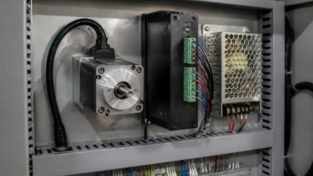
The electrical environment inside an industrial control cabinet is saturated with electromagnetic interference (EMI) generated by high-frequency PWM switching. Sending a fragile 5V TTL encoder signal across a machine frame exposes it to this noise. If the driver registers a stray voltage spike as an encoder pulse, the closed-loop algorithm will mistakenly "correct" the position, causing an erratic physical jump.
To guarantee signal integrity, industrial encoders utilize differential line drivers (EIA RS-422 standard). Instead of sending a single signal referenced to ground, the encoder sends two mirrored signals for each channel (A and A-not, B and B-not, Z and Z-not). If a magnetic field induces a noise spike in the cable, the spike affects both wires equally (common-mode noise). The receiver circuit at the drive reads only the voltage difference between the two wires, mathematically canceling out the noise. Engineers must specify differential outputs and utilize twisted-pair cabling with a grounded braided shield for all feedback installations exceeding one meter in length.
6. Engineering Selection Criteria for Motion Feedback
Question: How do automation engineers decide between specifying an optical incremental encoder and a magnetic absolute encoder for a new mechanical axis?
Answer: Engineers execute a decision matrix based on environmental hazards, startup sequence requirements, and budget. If the axis operates in a highly controlled environment (CNC milling, clean room) where maximum velocity loop smoothness is required and homing upon startup is acceptable, the optical incremental encoder provides the highest linearity per dollar. If the axis operates in an environment with high dust, heavy cutting fluids, or heavy vibration, and the mechanical design prohibits time-consuming homing routines (e.g., a multi-axis robotic arm where homing could cause physical collision), the magnetic multi-turn absolute encoder is mandatory.
Integration and Custom Feedback Solutions
Correctly pairing the sensing technology with the environmental operating parameters ensures the long-term reliability of the motion control architecture. Cymotorix engineers a comprehensive portfolio of actuation hardware, pairing our stepper motors and servos with application-specific optical, magnetic, incremental, and absolute feedback devices. Our engineering team assists OEMs in calculating the required resolution for velocity loop stability and specifying the correct IP-rated accessories for washdown environments. Technical datasheets, wiring schematics, and 3D CAD models are available through our download center. Contact our technical applications department to specify the optimal closed-loop feedback architecture for your machinery.
Frequently Asked Questions (FAQ)
Question: Why does my optical encoder fail when operating near large temperature fluctuations?
Answer: Large temperature swings cause the air inside the motor housing to expand and contract. If the encoder cover is not hermetically sealed, ambient humidity is drawn in. When the motor cools, the moisture condenses onto the optical glass disk, refracting the internal LED light beam and preventing the photodetector from reading the lines correctly, resulting in an immediate fault.
Question: What is the primary physical advantage of a magnetic encoder over an optical encoder?
Answer: Magnetic encoders do not require a line of sight to operate. The solid-state magnetic sensor and the rotating magnet can be heavily potted and sealed, making them completely immune to dust, oil, condensation, and mechanical shock that would normally shatter a glass optical disk.
Question: Why do servo drives require ultra-high-resolution 23-bit encoders?
Answer: The massive 8.3-million count resolution of a 23-bit encoder is not used to achieve sub-micron physical accuracy, as mechanical transmission backlash negates that precision. It is used to provide incredibly granular data to the drive's velocity control loop. This allows the drive to calculate extremely smooth speed derivatives, completely eliminating vibration and judder when the motor rotates at very low RPMs.
Question: What is the difference between a single-turn and a multi-turn absolute encoder?
Answer: A single-turn absolute encoder knows its exact position within one 360-degree rotation. If the motor is powered off and rotated manually past one full turn, the drive loses track of the total distance. A multi-turn absolute encoder utilizes an internal gear train, battery, or Wiegand wire to record both the current angular position and the total number of complete revolutions, maintaining total travel data regardless of power loss.
Question: Why is a differential line driver (A, A-, B, B-) necessary for industrial encoder wiring?
Answer: Industrial cabinets are filled with electrical noise (EMI) from switching power supplies and high-voltage PWM drives. Single-ended signals can absorb this noise, causing false position counts. A differential line driver sends two mirrored signals for each channel. The receiving drive subtracts the two signals, which naturally cancels out any electromagnetic noise picked up along the length of the cable.
Question: Do I need to perform a homing routine on an axis equipped with an incremental encoder?
Answer: Yes. Incremental encoders only output square waves representing relative movement. When the machine powers up, the controller has no reference to the actual physical coordinate. The machine must slowly rotate the motor until a physical limit switch is triggered (the home position) before it can establish a valid coordinate system for production.
-

Cymotorix
Stepper Motor & Servo Motor Manufacture
Cymotorix is a China-based motor manufacturer with 20+ years of experience producing hybrid stepper motors, AC servo motors, and matched drivers for OEM customers worldwide.