
Power Supply Selection Determines Real Stepper Performance
A stepper motor system reaches its specified torque only when the power supply, driver, winding, and motion profile are engineered as one electrical system. An undersized supply causes voltage sag during acceleration. An oversized or poorly protected supply can expose the driver to regenerative overvoltage during deceleration. Both conditions appear in the field as lost steps, driver faults, inconsistent positioning, or premature power-stage failure.
For most industrial stepper axes, the correct supply is selected from four inputs: the driver's permitted input range, the motor's set phase current, the required speed-torque point, and the number of axes that accelerate at the same time. A practical starting estimate is PPSU = Nsimultaneous × Iset × Vbus × 1.2. High-duty machines, vertical axes, and aggressive acceleration profiles require additional margin and regenerative-energy checks.
1. Define the Operating Point Before Selecting Hardware
Power supply selection should begin after the motion requirement is fixed. A NEMA frame alone does not define the electrical load. Two motors with the same frame can have different phase current, resistance, inductance, encoder options, and speed-torque behavior. The purchasing specification should therefore include the motor part number, the driver model, and the actual motion duty.
Record the following data before comparing power supplies:
- Motor rated phase current and the current value configured on the motor driver
- Motor phase resistance and inductance, especially when the axis must run above 500 RPM
- Target speed, acceleration time, load inertia, and transmission efficiency
- Number of axes and how many axes accelerate simultaneously
- Continuous run time, holding time, idle-current setting, and ambient temperature
- Driver input-voltage range, overvoltage threshold, and available braking or regeneration terminals
- Cable length between the supply, driver, and motor
This data allows the supply to be selected from an operating point rather than from a generic frame-size table. It also gives the motor supplier enough information to verify the complete motion set before production.
2. Why Motor Rated Voltage Is Not the Driver Bus Voltage
A stepper motor's low rated voltage is usually the calculated resistive drop across the winding at rated current: Vrated = Irated × Rphase. It is a thermal and resistance reference. It is not the recommended input voltage for a modern chopper driver.
A current-regulated driver applies a higher DC bus voltage to the winding and switches the output at high frequency. This action forces current to rise quickly, then limits the average current to the configured value. The winding behaves as an inductor in series with resistance. Its approximate current rise follows:
di/dt = (Vbus − I × R − Vback-EMF) / L
As speed increases, back-EMF rises and reduces the net voltage available to change winding current. A higher bus voltage restores current-rise capability, which helps the driver maintain the commanded current at higher pulse rates. This is the main reason a motor with a 3 V or 5 V winding rating may operate from a 24 V, 36 V, or 48 V driver supply when the driver is configured correctly.
The motor should never be connected directly to a DC supply at the bus voltage. The driver's current regulation is the protection mechanism. Correct wiring, current setting, and supply tolerance are required for safe operation.
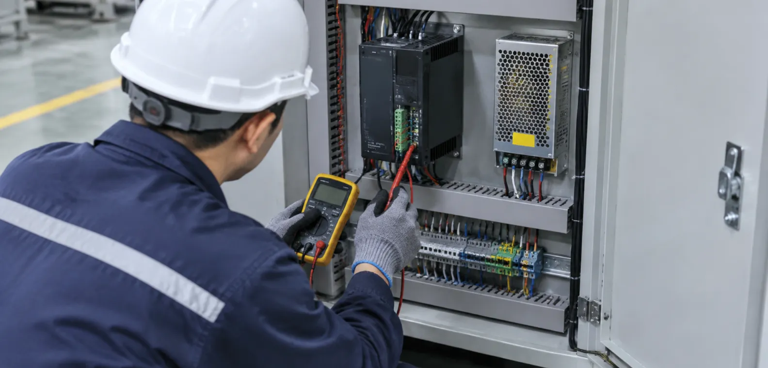
3. Select Bus Voltage from the Speed-Torque Requirement
Holding torque is measured at zero speed. Production equipment cares about torque at the required operating speed and during acceleration. If the speed-torque curve shows insufficient margin at the target RPM, increasing bus voltage within the driver's rated range is often the first electrical correction. Other corrections include reducing acceleration, selecting a lower-inductance winding, changing the transmission ratio, or moving to a larger frame.
The following ranges are engineering starting points for DC-input stepper systems. Final selection must stay inside the specific driver's input range and protection limits.
| Motor Frame / System Type | Common DC Bus Starting Range | Typical Selection Logic |
|---|---|---|
| NEMA 8 to NEMA 17 | 12–24 VDC | Compact instruments, light positioning axes, moderate speed |
| NEMA 23 to NEMA 24 | 24–48 VDC | General automation, laboratory equipment, packaging, small CNC |
| NEMA 34 | 48–80 VDC when supported | Higher torque at speed, faster acceleration, heavier machine axes |
| NEMA 42 and larger | High-voltage DC or AC-input drive | High-power axes where DC supply size, cable loss, and regeneration require system-level review |
A 24 V rail is common because it matches industrial control cabinets and standard DIN-rail supplies. A 48 V rail is preferred when the axis must maintain torque at higher speed or when cable current needs to be reduced. Higher voltage also increases switching stress and fault energy, so the driver's maximum input rating remains the upper boundary.
4. Calculate Supply Current and Wattage Conservatively
Use the Driver's Configured Current
The power calculation should use the phase-current value configured on the driver, which may be lower than the motor's maximum rating. If the axis does not require full holding torque, engineers often reduce current to limit motor heating. The reduced setting lowers the expected supply demand, but the machine must still pass the worst-case acceleration and load tests.
Apply a Practical Power Formula
For a first-pass quotation or cabinet layout, use:
PPSU ≥ Nsimultaneous × Iset × Vbus × 1.2
Where:
- PPSU is the minimum power-supply wattage
- Nsimultaneous is the number of axes that can accelerate at the same time
- Iset is the configured phase current per motor
- Vbus is the selected driver supply voltage
- 1.2 adds a 20% engineering margin
The corresponding supply-current requirement is:
IPSU ≥ PPSU / Vbus
This formula is intentionally conservative for many open-loop positioning axes because a chopper driver behaves like a power converter. The supply current is usually lower than the sum of both motor phase currents. It remains useful for procurement because it covers conversion losses, acceleration demand, and normal manufacturing variation. Continuous high-speed axes, vertical loads, and frequent reversal duty should use a 1.5–2.0 multiplier until test data confirms a lower value.
Worked Examples
| System | Calculation | Recommended Supply Class |
|---|---|---|
| One NEMA 17 axis at 1.5 A, 24 V bus | 1 × 1.5 × 24 × 1.2 = 43.2 W | 24 V / 60 W supply |
| One NEMA 23 axis at 3.0 A, 48 V bus | 1 × 3.0 × 48 × 1.2 = 172.8 W | 48 V / 200 W supply |
| Three NEMA 23 axes at 3.0 A, 36 V bus, all accelerate together | 3 × 3.0 × 36 × 1.2 = 388.8 W | 36 V / 400 W minimum; 500 W for sustained high duty |
| Two NEMA 34 axes at 5.0 A, 60 V bus, heavy acceleration | 2 × 5.0 × 60 × 1.5 = 900 W | 60 V / 900–1000 W supply, subject to regeneration review |
These examples establish a supply class. They do not replace loaded testing because motor inductance, driver efficiency, pulse frequency, transmission friction, and deceleration energy change the actual demand.
5. Correct the Estimate for Multi-Axis Motion and Duty Cycle
Many machines do not move all axes at full load at the same time. A pick-and-place axis may accelerate while another axis is holding. A 3D printer may distribute motion across several small motors. A CNC router can require simultaneous X, Y, and Z acceleration during aggressive toolpaths. The supply should match the worst credible motion state, including restart after a fault.
Use these corrections:
- Simultaneous acceleration: Count axes that can accelerate together, even if steady-state motion is lighter.
- Holding current: Axes that hold position for long periods contribute thermal load but less dynamic supply demand.
- Vertical axes: Gravity can assist deceleration in one direction and resist motion in the other. Treat this as a regenerative and safety case.
- High step frequency: Higher RPM increases mechanical power demand and back-EMF. Verify the torque curve at the selected bus voltage.
- Idle-current reduction: Lower standby current reduces heat, but the driver must return to running current before acceleration begins.
For machines with uncertain duty, data logging during a prototype run is the most reliable method. Measure bus voltage, supply current, driver temperature, motor case temperature, and position error over the longest realistic cycle.
6. Manage Regenerative Energy During Deceleration
A rotating motor and load store kinetic energy. During rapid deceleration, the motor can return energy to the DC bus. Most standard switching power supplies can source current but cannot absorb reverse current. If the bus capacitance and driver protection cannot absorb the returned energy, bus voltage rises until the driver reports an overvoltage fault or the power stage is damaged.
Risk increases with:
- Large rotor or load inertia
- High operating speed and short deceleration time
- Vertical or overhauling loads
- Low bus capacitance
- Bus voltage already near the driver's upper limit
Common controls are a longer deceleration ramp, additional bus capacitance approved by the driver manufacturer, a regeneration resistor or clamp module, and a supply voltage selected with margin below the driver's overvoltage threshold. A TVS device can absorb defined transients, but it should not be used as the primary method for continuous regenerative energy.
The complete check is: nominal bus + supply tolerance + measured regenerative rise < driver maximum input rating. The test should run at maximum speed, maximum load inertia, and the shortest planned deceleration.
7. Wiring, Grounding, and EMI Requirements
A correctly rated supply can still produce unstable motion if the cabinet wiring introduces voltage drop, noise, or grounding loops. Keep the power path short and use conductors sized for the calculated supply current with temperature margin. Twisted pairs are appropriate for DC bus and motor-phase leads. Signal wiring should be separated from motor power wiring, especially when encoders are used with a closed loop stepper motor.
Use a single protective-earth reference for the supply chassis, driver chassis, and machine frame where required by the equipment standard. Add a fuse or breaker on the input side and confirm that the supply's inrush current does not nuisance-trip upstream protection. For long cables, check voltage drop at peak demand and add local capacitance only within the driver's documented limits.
Disconnect power before changing motor wiring. Opening a motor phase while the driver is energized can create a high-voltage transient at the driver output. After shutdown, wait until the DC bus has discharged before touching terminals.
8. Validate the Power System Before Production Release
A production-ready supply decision should be supported by measured results. The minimum validation sequence is:
- Confirm the driver's configured current and microstep setting.
- Run cold-start and warm-start motion at maximum commanded speed.
- Apply the worst-case load and acceleration profile.
- Record bus voltage during acceleration, constant speed, and deceleration.
- Measure motor case and driver heatsink temperature over the full duty cycle.
- Test supply recovery after undervoltage, overvoltage, E-stop, and power interruption.
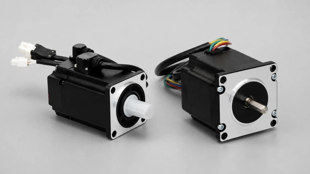
- Verify that a 2-phase stepper motor, closed-loop motor, or servo motor selected for the axis maintains the required position tolerance.
The pass criteria should come from the machine specification: no lost-position event, no driver fault, no excessive temperature rise, and no supply voltage excursion outside the driver's operating window.
Engineering Support and Motor-Driver Matching
Cymotorix supports OEM projects with stepper motors, servo motors, and matched drives for industrial motion systems. For power-supply verification, provide the motor model, configured phase current, driver model, target RPM, number of simultaneous axes, duty cycle, cable length, and cabinet temperature. Our engineering team can review the speed-torque requirement, bus-voltage selection, and regeneration risk before the bill of materials is fixed.
Product datasheets and dimensional drawings are available from the download center. For application review or a matched motor-driver recommendation, contact our application engineering department.
Frequently Asked Questions (FAQ)
Question: Can a NEMA 23 stepper motor run from a 12 V supply?
Answer: It can run if the driver accepts 12 V and the current is configured correctly, but torque at medium and high speed will usually be limited. For industrial NEMA 23 axes, 24–48 V is a more useful starting range because it provides additional voltage headroom against winding inductance and back-EMF.
Question: Why does the supply ammeter show less current than the motor's phase-current rating?
Answer: The chopper driver converts high-voltage, lower-current input power into the controlled winding current required by the motor. Phase current and supply current are not the same measurement. The supply current also changes with speed, load, duty cycle, and driver efficiency.
Question: Should the power supply current equal the sum of both motor phase currents?
Answer: No. Adding both phase currents usually overestimates DC supply demand in a current-regulated stepper system. Use the configured phase current, number of simultaneous axes, bus voltage, and a margin factor for the first estimate, then validate with loaded testing.
Question: What happens if the power supply is undersized?
Answer: The bus voltage can sag during acceleration or simultaneous axis motion. The driver may enter undervoltage protection, reduce current, fault, or reset. The machine can lose position or produce inconsistent motion even though the motor and driver are individually rated correctly.
Question: How do I prevent overvoltage during rapid deceleration?
Answer: Start with a longer deceleration ramp and confirm the measured bus rise. If voltage still approaches the driver limit, use an approved regeneration resistor, clamp module, or additional bus capacitance. Keep nominal supply voltage and regeneration headroom below the driver's maximum input rating.
Question: Is a higher supply voltage always better for stepper performance?
Answer: No. Higher voltage improves current rise and high-speed torque capability, but it also increases switching stress, fault energy, and the importance of regeneration control. Select the lowest bus voltage that meets the required speed-torque point with stable thermal and fault behavior.
Question: What information should an OEM send when asking for a motor, driver, and power-supply review?
Answer: Send the motor part number, phase-current setting, phase inductance if available, driver model, desired bus voltage, target speed and acceleration, number of simultaneous axes, duty cycle, ambient temperature, cable lengths, and any vertical or overhauling load condition.
-

Cymotorix
Stepper Motor & Servo Motor Manufacture
Cymotorix is a China-based motor manufacturer with 20+ years of experience producing hybrid stepper motors, AC servo motors, and matched drivers for OEM customers worldwide.