
The Engineering Reality of Stepper Motor Resonance
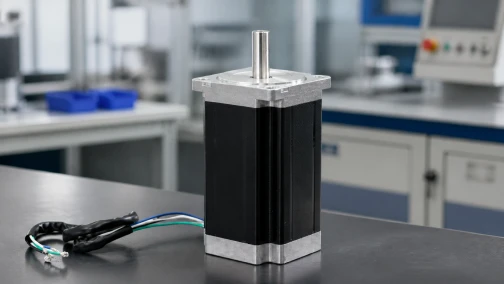
Vibration and acoustic noise are inherent byproducts of open-loop step actuation. Because a hybrid stepper motor moves in discrete angular increments rather than continuous rotation, the rotor is subjected to continuous acceleration and deceleration pulses. In high-precision applications such as optical inspection stages, medical imaging, and CNC surface finishing, this mechanical oscillation translates directly into positional tracking errors, surface finish artifacts, and unacceptable acoustic emissions.
Engineers troubleshooting an unstable axis often default to replacing the motor or increasing the current limit. This approach rarely solves the underlying physics. Motor vibration originates from two distinct domains: mechanical resonance caused by the rotor's mass-spring characteristics, and electrical noise induced by the driver's current commutation. Resolving these issues requires isolating the source through systematic diagnostics, tuning the drive electronics, and applying targeted mechanical damping. This technical manual details the mechanisms behind stepper vibration and outlines industrial solutions for achieving smooth axis operation.
1. The Physics of Rotor Ringing and Mechanical Resonance
A standard 2-phase stepper motor has 200 physical full steps per revolution. Each time the driver sends a step pulse, the stator magnetic field rotates by 1.8 degrees. The permanent magnet rotor accelerates to catch up with this new magnetic alignment. Because the rotor possesses mass (inertia) and the magnetic field acts as an invisible torsional spring (holding torque), the rotor does not stop instantly upon reaching the target coordinate. It overshoots, gets pulled back, and oscillates microscopically before settling. This behavior is called rotor ringing.
Every mass-spring system has a natural resonant frequency. For standard NEMA 17 and NEMA 23 motors, this natural frequency typically falls between 100 and 200 full steps per second (roughly 30 to 60 RPM). If the step pulse frequency matches the natural frequency of the rotor, the ringing amplitude compounds with every subsequent step. This creates the primary resonance band. When operating within this band, the motor vibrates violently, loses its effective torque, and frequently stalls, even under no-load conditions.
2. Electrical Noise: Chopper Drives and Current Ripple
While low-frequency rumble originates from mechanical resonance, high-frequency whine and hiss are electrical phenomena. Modern bipolar motor drivers operate using constant-current chopper circuits. Instead of applying a flat DC voltage, the drive applies a high-voltage pulse and rapidly switches it on and off (Pulse Width Modulation, or PWM) to maintain a specific target current.
This PWM switching typically occurs at frequencies between 20 kHz and 40 kHz. Although this frequency is above the upper limit of human hearing, it causes magnetostriction—microscopic physical expansions and contractions of the motor's iron stator laminations. This vibration generates an audible high-pitched squeal. Furthermore, if the drive's current control loop is poorly tuned, the actual current will oscillate around the target value. This current ripple creates minor torque fluctuations that manifest as audible hiss and rough low-speed rotation.
3. Understanding PWM Decay Modes (Slow, Fast, and Mixed)
The severity of current ripple is heavily dependent on the driver's decay mode setting. When the PWM switch turns off, the inductive energy stored in the motor winding must be dissipated safely. The path the drive forces this current to take is called the decay mode.
- Slow Decay: The current recirculates through the lower transistors of the H-bridge. Current decreases very slowly, resulting in low current ripple and quiet operation at standstill. However, at higher speeds, slow decay cannot discharge the coil fast enough, leading to distorted current waveforms and severe torque loss.
- Fast Decay: The current is forced back into the power supply. The coil discharges rapidly, allowing excellent high-speed current tracking. The drawback is massive current ripple, causing the motor to run loudly and aggressively at low speeds.
- Mixed Decay: The industry standard for CNC and automation. The drive uses fast decay for a percentage of the off-time to track the falling edge of the sine wave, then switches to slow decay to minimize ripple. Adjusting the mixed decay ratio (e.g., 30% fast, 70% slow) is a primary method for tuning out electrical vibration.
4. Diagnostic Workflow: Isolating Mechanical vs. Electrical Issues
Before applying solutions, engineers must correctly identify the source of the vibration. Applying mechanical dampers to an electrically noisy system yields no improvement.
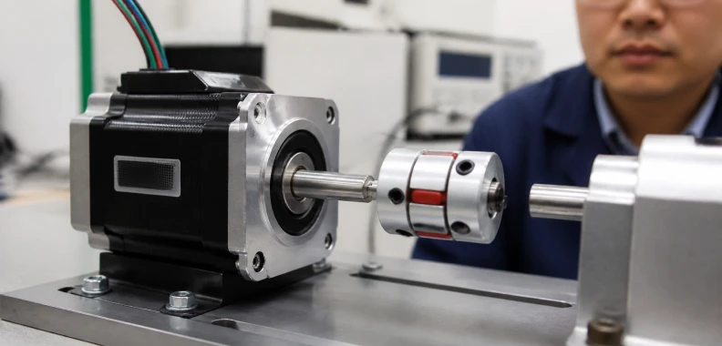
Step 1: The Uncoupled Spin Test. Disconnect the motor from the load and remove any couplings from the shaft. Run the motor across its speed range. If the vibration disappears completely, the problem is mechanical resonance exacerbated by the specific inertia of the attached load. If the motor still vibrates violently at a specific low speed (e.g., 150 RPM), you have found the primary, unloaded resonance band.
Step 2: The Standstill Noise Test. Power the motor and command zero movement. If the motor emits a loud, high-pitched hiss or whine while stationary, the issue is electrical. The chopper frequency or the decay mode is poorly matched to the winding inductance.
5. Fix 1: Microstepping Implementation and Limitations
The most immediate and effective electrical fix for mechanical resonance is microstepping. A microstepping drive proportionally divides current between Phase A and Phase B, creating sub-steps. Setting a drive to 1/8 microstepping requires 1,600 pulses to complete one revolution. This smooths the discrete 1.8-degree physical step into smaller, continuous increments, drastically reducing the energy of each acceleration pulse and minimizing rotor ringing.
Modern digital drives offer up to 256 microsteps per full step, synthesizing a near-perfect sine wave. However, microstepping does not increase mechanical accuracy beyond the motor's physical tolerance (typically +/- 5%). Engineers should default to 8, 16, or 32 microsteps for general automation. Extremely high microstep settings demand high-frequency pulse trains from the controller, which can exceed the bandwidth of standard optocouplers without yielding additional smoothness.
6. Fix 2: Mechanical Damping and Inertia Matching
When software and drive tuning cannot clear a resonance band, mechanical intervention is required. Adding damping alters the mass-spring equation of the system.
- Elastomer Couplings: Replacing rigid shaft couplings with elastomer spider couplings or zero-backlash bellows introduces mechanical compliance. The flexible element acts as a shock absorber, dissipating the ringing energy before it reaches the lead screw.
- Inertia Dampers: Attaching a physical damper to the rear shaft of the motor adds stabilizing mass. Houdaille dampers (viscous dampers) contain a free-spinning internal inertia mass suspended in silicone fluid. When the rotor rings, the internal mass shears against the fluid, converting the vibration energy into heat.
- Inertia Matching: Adjusting the transmission ratio (via pulleys or gearboxes) to bring the load-to-rotor inertia ratio below 5:1 natively prevents the mechanical load from dominating the motor's magnetic stiffness.
7. Fix 3: Advanced Drive Algorithms and Hardware Upgrades
If standard bipolar stepper limits cannot meet the acoustic requirements of an application, upgrading the underlying hardware architecture is necessary.
Anti-Resonance Drives: Advanced digital signal processing (DSP) stepper drives monitor the back-EMF generated by the motor. When the drive detects phase shifts indicative of resonance, it dynamically alters the current command in real-time to cancel the oscillation, allowing the motor to push through the primary resonance band seamlessly.
3-Phase Stepper Motors: Upgrading to a 3-phase stepper motor fundamentally changes the internal geometry. These motors typically feature a 1.2-degree step angle rather than 1.8 degrees. The higher pole count and tighter step angle inherently reduce ringing amplitude, making them substantially quieter and smoother out of the box, especially in optical tracking or laser cutting applications.
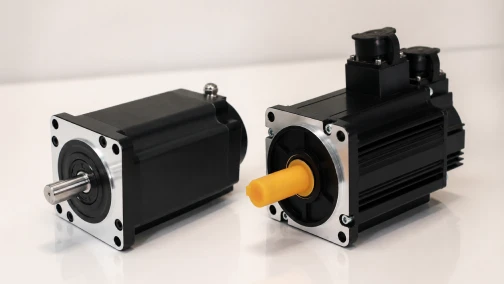
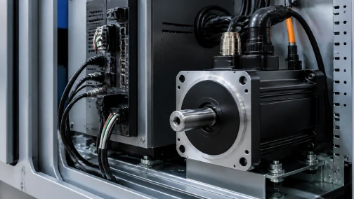
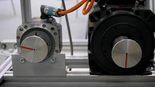
Closed-Loop Systems: The definitive solution for vibration is moving to a closed-loop stepper motor. By integrating a high-resolution absolute encoder, the drive executes Field-Oriented Control (FOC). It tracks the exact rotor position and supplies only the precise current vector required to move to the next coordinate, rather than blindly blasting full current into the stator. This completely eliminates resonance, drastically reduces heat, and matches the smooth acoustic profile of an AC servo.
Engineering Support for Precision Motion
Vibration mitigation requires a holistic analysis of payload inertia, drive electronics, and mechanical transmission. Cymotorix supplies a comprehensive range of low-vibration actuation solutions, including DSP-based anti-resonance drives, viscous dampers, and high-precision accessories. Our engineering team routinely assists equipment builders in calculating inertia ratios and specifying custom decay-tuned systems to meet strict hospital or laboratory acoustic standards. Contact our technical sales department to discuss your specific operational challenges and upgrade your motion architecture.
Frequently Asked Questions (FAQ)
Question: Why does my stepper motor vibrate violently and stall at exactly 150 RPM, but run perfectly at 500 RPM?
Answer: You are hitting the primary mechanical resonance band. At approximately 150 RPM, the frequency of your step pulses perfectly matches the natural mass-spring frequency of your motor and load. The ringing energy compounds until the rotor desynchronizes from the stator field. You must accelerate through this speed band quickly, increase microstepping, or add mechanical damping.
Question: Will increasing the drive current stop my motor from vibrating?
Answer: Usually, no. In fact, increasing the current amplifies the holding torque, which acts as the "spring" in the mass-spring equation. A stiffer spring often makes resonance and ringing worse, not better. Furthermore, excessive current generates unnecessary heat. You should only use the minimum current required to reliably move your load.
Question: Does setting my driver to the maximum microstep resolution (e.g., 256) provide the best vibration reduction?
Answer: Not necessarily. While upgrading from half-step to 16 or 32 microsteps drastically reduces vibration by synthesizing a sine wave, diminishing returns occur beyond this point. Extremely high settings (like 256) require very high pulse frequencies from your controller, which can cause signal degradation, while offering no measurable improvement in physical smoothness or accuracy over 32 microsteps.
Question: Why does my motor emit a high-pitched whine even when it is completely stopped?
Answer: This is electrical noise caused by the driver's PWM chopper circuit. The drive is rapidly switching voltage on and off at 20 kHz or higher to maintain the holding current. This frequency induces magnetostriction in the motor's steel core. You can mitigate this by adjusting the driver's decay mode to a slower setting or enabling the drive's auto-standstill current reduction feature.
Question: What is a viscous inertia damper and how does it help?
Answer: A viscous inertia damper (often called a Houdaille damper) is a mechanical puck mounted to the rear shaft of the stepper motor. It contains a heavy internal mass floating in viscous silicone fluid. When the motor shaft rings or vibrates, the internal mass resists the sudden movement, shearing the fluid. This absorbs the resonance energy and turns it into heat, instantly stabilizing the axis.
Question: How do closed-loop stepper motors eliminate resonance vibration?
Answer: Standard open-loop steppers suffer from resonance because the drive forces current regardless of the rotor's actual position. A closed-loop stepper uses a high-resolution encoder to track the rotor in real-time. Using Field-Oriented Control (FOC), the drive continually adjusts the current vector to precisely match the load demand, completely preventing the rotor from overshooting and ringing.
-

Cymotorix
Stepper Motor & Servo Motor Manufacture
Cymotorix is a China-based motor manufacturer with 20+ years of experience producing hybrid stepper motors, AC servo motors, and matched drivers for OEM customers worldwide.