
The Mechanical Imperative of Integrated Linear Actuation
Translating the rotary motion of a servo motor into precise linear displacement is the core mechanical function of CNC machinery, automated dispensing platforms, and industrial press equipment. The traditional approach to building a linear axis involves connecting a standard rotary motor to a discrete ball screw using an elastomer shaft coupling. While functional, this decoupled architecture introduces mechanical compliance, torsional wind-up, and alignment errors that degrade the system's dynamic response and positional accuracy.
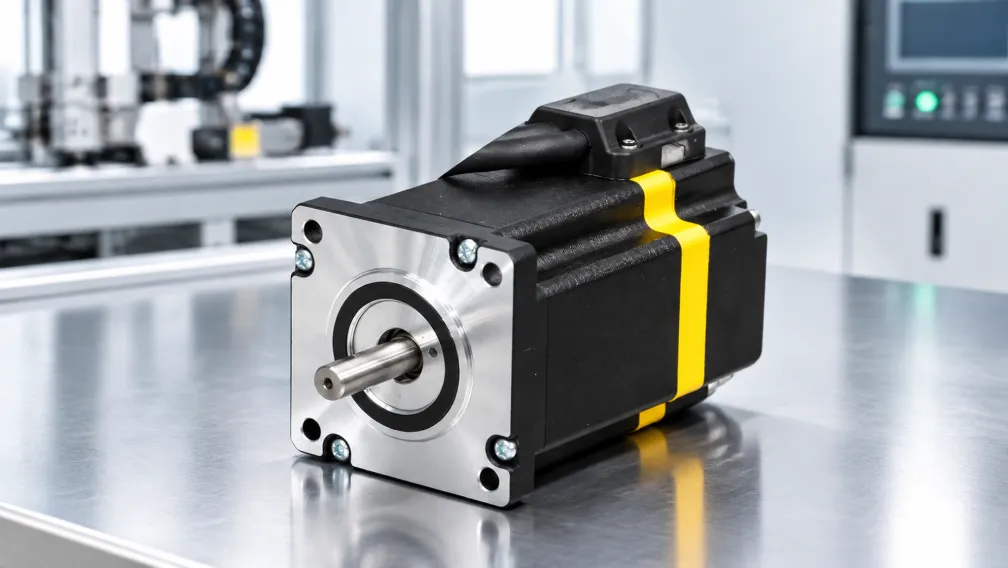
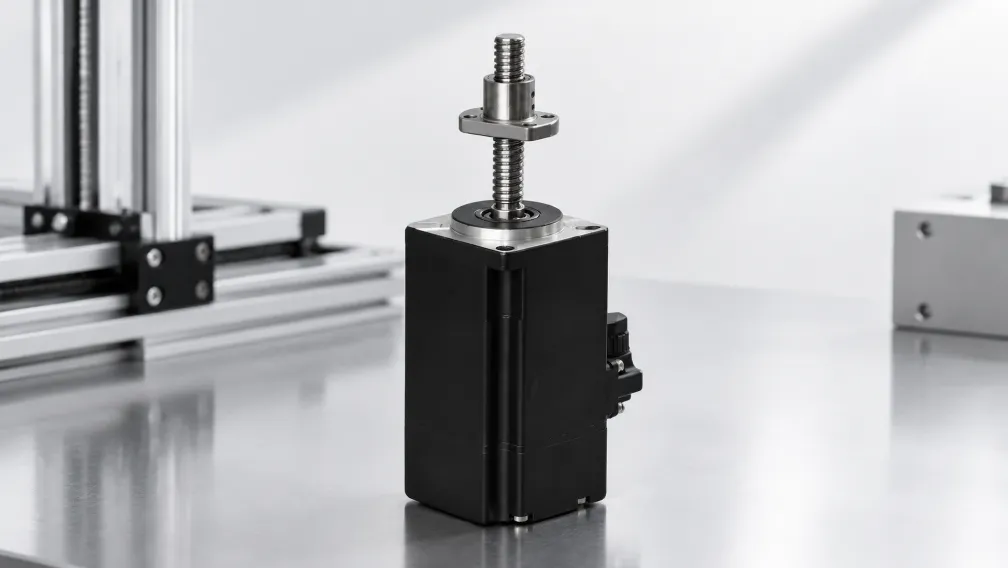
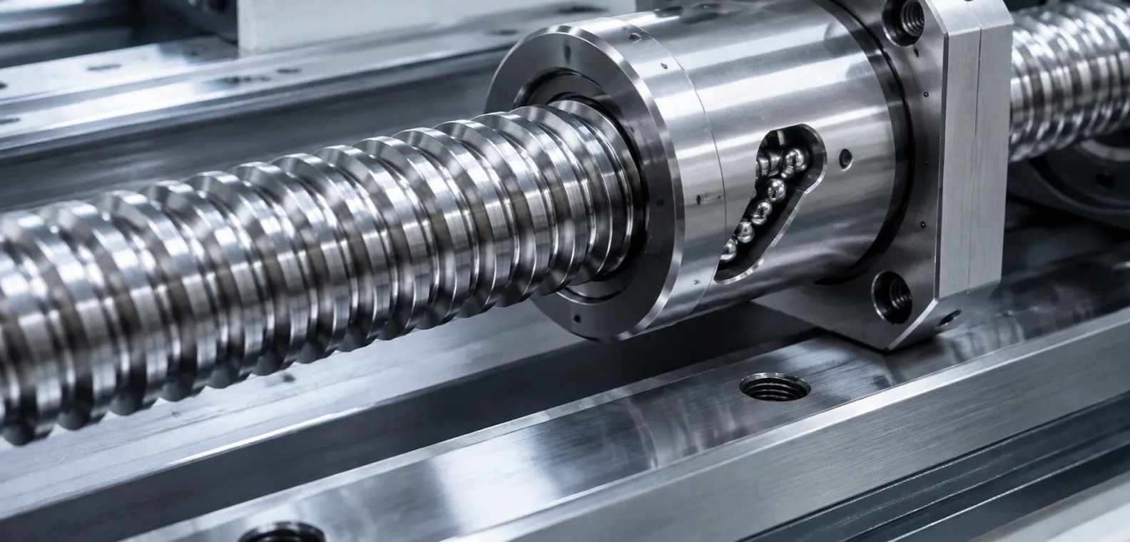
To achieve maximum structural stiffness and eliminate coupling backlash, engineers deploy integrated ball screw servo motors. In this architecture, the threaded ball screw is machined directly into the motor's rotor shaft, or the rotor is hollowed to encapsulate a captive nut. This creates a single, rigid electromechanical actuator. This technical manual evaluates the internal kinematics of integrated ball screw servos, details the calculus of linear thrust and inertia reflection, and establishes the engineering boundaries for specifying these actuators in high-precision automation.
1. Architectural Advantages: Eliminating Torsional Compliance
In a standard linear axis, the elastomer or bellows coupling acts as a mechanical spring between the motor and the screw. When the servo drive commands a violent acceleration, the coupling momentarily twists (winds up) before transmitting the full torque to the screw. This micro-delay forces the servo drive's Proportional-Integral-Derivative (PID) loop to compensate for the mechanical lag, often resulting in velocity ripple and extended settling times at the end of a rapid traverse.
An integrated ball screw servo motor eliminates the coupling entirely. The rotor's magnetic core and the ball screw are a single, continuous piece of hardened steel. This zero-compliance geometry ensures that every microscopic rotational movement of the rotor translates instantaneously into linear displacement at the ball nut. The elimination of the coupling also shortens the overall physical length of the actuator assembly by 10% to 20%, allowing engineers to fit high-thrust axes into highly restricted machine footprints.
2. The Calculus of Screw Lead and Linear Resolution
Specifying a ball screw servo requires aligning the mechanical "lead" of the screw with the electronic resolution of the encoder. The lead (p) is defined as the linear distance the ball nut travels during one complete 360-degree rotation of the screw, typically measured in millimeters (e.g., 5mm, 10mm, or 20mm per revolution).
The theoretical linear resolution of the axis is determined by dividing the screw lead by the encoder's pulses per revolution (PPR):
Linear Resolution = p / Encoder PPR
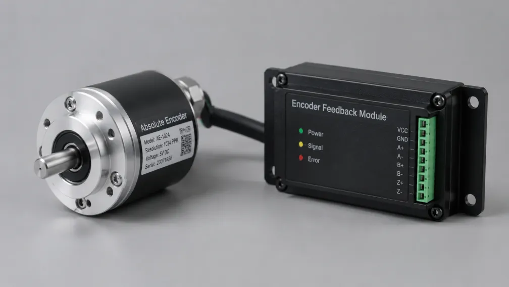
If a servo motors platform is equipped with an industrial 23-bit absolute encoder (8,388,608 counts per revolution) driving a 5mm lead screw, the theoretical linear resolution is 5mm / 8,388,608 = 0.00000059 mm per encoder count. While physical machining tolerances (such as ball bearing deformation and thermal expansion) prevent the axis from achieving sub-nanometer physical accuracy, this extreme electronic resolution guarantees that the drive's velocity loop receives perfectly smooth, continuous feedback, eliminating low-speed mechanical judder.
3. Calculating Linear Thrust Force and Motor Torque
Engineers must convert the continuous and peak rotational torque of the motor into linear thrust force to verify the actuator can push the required payload or execute the required pressing operation. The relationship between motor torque (T) and linear thrust force (F) is governed by the screw lead (p) and the mechanical efficiency of the recirculating ball nut (η):
F = (T × 2π × η) / p
Note: When calculating, torque must be in Newton-meters (Nm), the lead must be in meters (m), and force is yielded in Newtons (N). Ball screws typically operate at highly efficient levels, with η ranging from 0.85 to 0.95 due to rolling contact, compared to the 0.30 to 0.50 efficiency of sliding-contact Acme lead screws.
If an integrated servo motor outputs a continuous torque of 2.5 Nm through a 10mm (0.01m) lead screw with 0.90 efficiency, the continuous linear thrust force is: F = (2.5 × 2π × 0.90) / 0.01 = 1,413 Newtons (approximately 144 kg of pushing force). For high-speed punch presses or riveting machines, the drive can momentary push 300% of this value (4,239 N) during the peak overload window.
4. The Physics of Inertia Reflection (The Screw Ratio)
One of the primary benefits of driving a load through a ball screw rather than using a direct-drive linear motor is the dramatic reduction of reflected inertia. Heavy payloads attached to the ball nut are mathematically scaled down by the screw's lead before the motor rotor feels their mass.
The mass inertia reflected to the motor shaft (J_mass) is calculated as:
J_mass = m_load × (p / 2π)²
Because the lead (p) is divided by 2π and then squared, the reduction factor is massive. A 100 kg payload driven by a 5mm (0.005m) lead screw reflects an inertia of only: 100 × (0.005 / 2π)² = 0.000063 kg·m². This extremely low reflected inertia allows relatively small servo motors to accelerate heavy machine gantries at rates exceeding 2G without destabilizing the closed-loop velocity algorithm.
5. Mechanical Limits: Critical Speed and Column Buckling
While the servo motor can theoretically spin at 5,000 RPM, the physical length of the ball screw strictly bounds the maximum allowable velocity. A long, unsupported rotating shaft will begin to whip (resonate transversely) at its "critical speed." This violent vibration instantly destroys the ball nut bearings and bends the shaft.
Critical speed is determined by the screw's root diameter, the unsupported length between the bearing mounts, and the end-fixity (e.g., fixed-free, supported-supported, fixed-fixed). Engineers must calculate the critical speed limit for the specific stroke length and ensure the servo drive's maximum RPM parameter is clamped safely below 80% of this mechanical threshold.
For vertical Z-axis applications or heavy pressing operations, engineers must also calculate the column buckling load. Pushing a heavy load creates compressive stress on the screw shaft. If the thrust force exceeds the buckling limit of the shaft's diameter and length, the screw will permanently bow. Integrated actuators with thicker shaft diameters (e.g., 16mm or 20mm) are mandatory for high-thrust, long-stroke deployments.
6. Engineering Selection Criteria for Linear Actuation
Question: How do automation engineers decide between specifying an integrated ball screw servo motor and a direct-drive linear motor for a new machine axis?
Answer: Engineers execute a decision matrix based on stroke length, thrust force, and budget. If the axis requires massive continuous pushing force, operates vertically against gravity, or must be heavily cost-optimized, the ball screw servo is the mandatory choice due to its high mechanical advantage and fail-safe holding capabilities. If the axis requires nanometer-level absolute precision with zero mechanical wear, travels over extreme stroke lengths (exceeding 2 meters where ball screw whip becomes prohibitive), and budget is unconstrained, a direct-drive linear ironless motor is specified.
7. Axial Load Management and Thrust Bearings
Standard rotary motors utilize deep-groove radial ball bearings designed primarily to support the spinning rotor, not to absorb heavy axial (push/pull) loads. In a standard decoupled axis, a dedicated bearing block containing angular contact bearings supports the ball screw and absorbs the axial thrust, protecting the motor.
In an integrated ball screw servo motor, the motor's internal bearings must handle the entire axial load of the machine. Therefore, these specialized motors are manufactured with oversized, high-capacity angular contact thrust bearings packed directly into the front motor flange. When specifying an integrated actuator, engineers must verify that the machine's required continuous thrust does not exceed the dynamic load rating (C) of these internal thrust bearings to guarantee a 20,000-hour operational lifespan.
Engineering Support and Drive Integration
Specifying an integrated linear actuator requires balancing continuous thrust forces against critical speed limits and bearing lifespans. Cymotorix engineers a complete portfolio of rotary and integrated linear motion hardware, combining high-efficiency ball screws with advanced closed-loop motor technology. Our technical department supplies complete 3D CAD models, critical speed calculation charts, and compatible RS3 servo drive pairings optimized for high-bandwidth linear interpolation. Access detailed dimensional drawings and technical datasheets via our download center, or contact our application engineering department to specify the optimal linear actuation architecture for your press or CNC equipment.
Frequently Asked Questions (FAQ)
Question: What is the primary advantage of integrating the ball screw directly into the servo motor rotor?
Answer: The integrated architecture eliminates the flexible shaft coupling entirely. This removes torsional wind-up, zero-crossing backlash, and resonance points associated with the coupling, creating a perfectly rigid mechanical link. It also significantly reduces the total physical length of the actuator, allowing it to fit into highly compact machine spaces.
Question: How does the screw lead affect the acceleration capabilities of the servo motor?
Answer: A smaller screw lead (e.g., 5mm per revolution) acts as a larger mechanical gear reduction. It dramatically reduces the mass inertia reflected to the motor and multiplies the linear thrust force, allowing a small motor to accelerate heavy loads rapidly. However, a small lead requires the motor to spin much faster to achieve the same linear top speed.
Question: What happens if I command the ball screw servo motor to run faster than its critical speed?
Answer: Exceeding the critical speed induces severe transverse resonance, commonly known as screw whip. The long metal shaft will begin to vibrate violently like a guitar string, which will instantly shatter the internal recirculating ball bearings in the nut and permanently bend the screw shaft.
Question: Can an integrated ball screw servo motor handle heavy pressing or stamping operations?
Answer: Yes, provided the motor is specifically designed for it. Integrated actuators used for pressing must be built with heavy-duty angular contact thrust bearings in the front flange. Standard radial bearings will be instantly crushed by heavy axial compressive forces. You must also verify that the peak force remains below the column buckling limit of the screw.
Question: Why do engineers use ball screws instead of standard Acme or trapezoidal lead screws in servo applications?
Answer: Ball screws use recirculating steel balls to create rolling contact, achieving mechanical efficiencies of 90% or higher with near-zero backlash. Standard lead screws rely on sliding friction, which drops efficiency below 50%, generates massive waste heat at high speeds, and suffers from rapid wear and unpredictable backlash, making them unsuitable for closed-loop servo precision.
Question: How do I prevent a vertical ball screw axis from crashing down when power is lost?
Answer: Due to the high efficiency of ball screws, they can easily back-drive under the force of gravity. A vertical axis must be specified with an integrated electromagnetic holding brake mounted to the rear of the servo motor. When the drive cuts power, the brake engages instantaneously, locking the rotor and holding the payload safely in position.
-

Cymotorix
Stepper Motor & Servo Motor Manufacture
Cymotorix is a China-based motor manufacturer with 20+ years of experience producing hybrid stepper motors, AC servo motors, and matched drivers for OEM customers worldwide.