
Why Servo Motor Sizing Is a Thermal and Dynamic Problem
An undersized servo motor faults out on thermal overload during the first production ramp. An oversized one adds rotor inertia the axis does not need, slows the dynamic response, and costs more than the application justifies. Servo sizing also differs from stepper sizing in one fundamental way: a servo operates inside a continuous feedback loop, so the selection criteria extend beyond raw torque to thermal duty over the full motion cycle and to the inertia relationship between motor and load. Getting either criterion wrong produces a system that passes bench testing and fails in the field.
This guide presents the sizing workflow our engineers apply when specifying AC servo motors for OEM equipment: torque classification, RMS torque calculation, inertia ratio verification, gearbox leverage, torque-speed curve validation, frame selection, and drive matching. The friction and gravity torque formulas follow the same mechanics covered in our stepper motor sizing guide; this article concentrates on the criteria specific to servo systems.
1. Continuous, Peak, and RMS Torque: The Three Ratings That Decide the Selection
Every servo datasheet carries two torque lines. Continuous torque, sometimes labeled rated torque, is the torque the motor can sustain indefinitely without exceeding its winding temperature limit. Peak torque is the short-duration maximum, typically available for a few seconds during acceleration bursts, limited by current and magnetic saturation. A third value does not appear on the datasheet at all: RMS torque, the thermally equivalent torque of the actual motion cycle, and it must be calculated.
The sizing rule is strict: the motor's continuous torque rating must exceed the calculated RMS torque of the duty cycle, and the peak rating must exceed the maximum instantaneous torque. Selecting on peak torque alone is the most common cause of thermal faults in commissioning, because a motor can accelerate a load perfectly for hours before the winding temperature climbs past its limit and the drive trips.
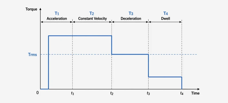
RMS torque compresses the full motion profile into one thermal number. The profile is divided into phases, typically acceleration, constant velocity, deceleration, and dwell, and the formula is:
Trms = √[(T1²·t1 + T2²·t2 + T3²·t3 + T4²·t4) / (t1 + t2 + t3 + t4)]
Dwell time counts in the denominator, which is why a machine with generous pauses between moves can run a smaller motor than the same mechanism on a tight cycle. As a working margin, keep the calculated RMS torque at or below 70 to 80% of the motor's continuous rating. That headroom absorbs load variation, ambient temperature above the 40°C test condition, and friction growth as the mechanics wear in.
2. Calculating Required Torque and Speed
The instantaneous torque at the motor shaft follows T = J × α + Tfriction + Tload, where J is the total inertia reflected to the motor shaft, α is angular acceleration, and Tload covers process forces such as cutting pressure or gravity on a vertical axis. The friction and gravity conversion formulas for ball screw, belt, and rack drives are documented in the stepper sizing guide linked above and apply unchanged here. The two outputs that matter are the peak instantaneous torque during acceleration and the RMS torque over the complete cycle including dwell.
Speed is the second check. Convert the required linear velocity into motor RPM using the screw lead or pulley ratio, and confirm the operating point sits at or below the motor's rated speed. Servos deliver their best efficiency near rated speed, and running continuously far below it wastes the motor's capability, a problem a gearbox usually solves better than a larger frame.
3. The Inertia Ratio Check: The Dynamic Stability Criterion
The load-to-rotor inertia ratio compares the total load inertia reflected to the motor shaft against the motor's own rotor inertia. Because a servo regulates position through a high-bandwidth feedback loop, this ratio directly governs how stiff, fast, and stable the axis can be tuned. A high ratio means the load dominates the system dynamics: loop gains must be reduced to prevent oscillation, settling time stretches, and following error grows.
Practical guidelines used across the industry:
| Inertia Ratio (Jload : Jrotor) | Expected Behavior |
| 1:1 to 3:1 | Excellent controllability; suits high-dynamic indexing and robotics |
| 3:1 to 5:1 | Acceptable for most industrial axes with standard tuning |
| 5:1 to 10:1 | Tunable but sluggish; requires careful gain adjustment |
| Above 10:1 | Poor settling and oscillation risk; add a gearbox or larger motor |
Modern drives include automatic inertia identification, where the drive excites the axis in both directions and measures the ratio directly. This feature speeds up commissioning, but it cannot fix a mechanically bad ratio; it only tunes around one. When the calculation lands above 10:1, the correct fix is mechanical.
4. The Gearbox as a Sizing Lever
A reducer with ratio N multiplies output torque by N, divides output speed by N, and divides the load inertia reflected to the motor shaft by N². The squared term is the powerful one. A load that reflects to a 30:1 ratio direct-coupled drops to roughly 3.3:1 behind a 3:1 planetary gearbox, moving the axis from untunable to comfortable without touching the motor size. The minimum ratio needed to hit a target inertia ratio follows Nmin = √[Jload / (target × Jrotor)], rounded up to the next standard ratio.
Worked example: a rotary indexing table carries 0.02 kg·m² of load inertia. Direct-coupled to a servo with 0.0006 kg·m² rotor inertia, the ratio is 33:1 and the axis will not settle cleanly. Adding a 5:1 reducer cuts the reflected inertia to 0.0008 kg·m², a 1.3:1 ratio, while multiplying the available torque fivefold. The trade-offs are backlash, typically 4 to 12 arc-minutes for standard planetary stages and 1 to 3 arc-minutes for precision grades, plus the reducer's own inertia and cost. Our planetary gearboxes, encoders, and brakes mount directly to the motor and ship as a tested assembly.
5. Reading the Servo Torque-Speed Curve
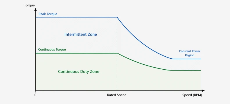
The servo torque-speed curve divides the operating envelope into two zones. The continuous duty zone, below the continuous torque line, can be sustained indefinitely. The intermittent zone, between the continuous and peak lines, is available only for the short durations the manufacturer specifies. Every steady-state operating point must land inside the continuous zone; acceleration points may enter the intermittent zone within its time limit.
Two curve characteristics matter for sizing. First, servo torque stays essentially flat from zero speed up to rated speed, which is the opposite of the stepper's steep decay and the reason servos dominate high-speed axes. Second, above rated speed the drive reaches its voltage limit and torque falls into the constant-power region. Published curves assume a 40°C ambient; motors running inside hot enclosures need the continuous line derated, so verify the test conditions before trusting a catalog curve.
6. Frame Size Selection: 40 mm Through 180 mm Flange
Once RMS torque, peak torque, and speed are fixed, frame selection follows standard servo power classes. The table below maps typical continuous torque ranges at a 3,000 rpm rated speed to common flange sizes; always confirm against the specific datasheet.
| Flange | Typical Power Range | Typical Continuous Torque | Common Axes |
| 40 mm | 50–100 W | 0.16–0.32 N·m | Small conveyors, lab automation |
| 60 mm | 200–400 W | 0.64–1.27 N·m | Pick-and-place, light gantries |
| 80 mm | 400 W–1 kW | 1.27–3.18 N·m | CNC feed axes, packaging machines |
| 110 mm | 1.2–1.8 kW | 3.8–5.7 N·m | Medium gantries, indexing tables |
| 130 mm | 1.5–3 kW | 4.8–9.6 N·m | Heavy CNC axes, presses |
| 180 mm | 3–5.5 kW | 9.6–17.5 N·m | Large spindles, heavy automation |
Target 50 to 70% utilization of continuous torque at the calculated RMS point. A motor running at 95% of its thermal rating has no margin for enclosure heat or mechanical wear, while a motor at 20% utilization carries rotor inertia and purchase cost the axis never uses.
7. Matching the Servo Drive, Power Supply, and Brake
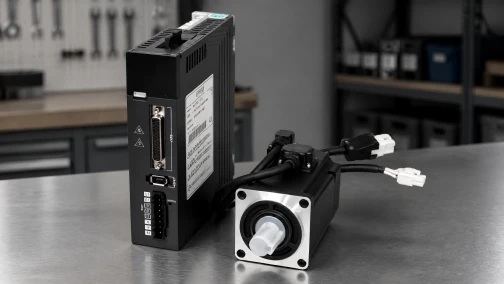
The drive's continuous and peak current ratings must cover the motor's requirements with margin, because available torque is proportional to available current. Undersizing the drive clips peak torque during acceleration and shows up as following-error faults under load. Our RA3 servo drive and RS3 servo drive series are matched to the motor range at the factory, with datasheets listing the approved pairings.
Two electrical details complete the check. High-inertia axes pump regenerative energy back into the DC bus during deceleration, and the drive's internal braking resistor has a finite capacity; if the deceleration energy of the reflected inertia exceeds it, an overvoltage alarm results and an external resistor is required. Vertical axes additionally need a holding brake, since the servo loop cannot hold position when power drops. Specify the brake on the motor at order time rather than retrofitting it.
Get a Motor and Drive Recommendation From Our Engineers
Servo sizing rewards exact data. Send us your axis mass, transmission geometry, motion profile, and duty cycle, and our engineers will return a complete motor and drive recommendation, typically within 24 hours. Datasheets, dimension drawings, and 3D CAD models for the full range are in our download center, and standard samples ship in 3 to 5 days. Contact our engineering team to start the selection process.
Frequently Asked Questions (FAQ)
Question: What is the difference between continuous torque and peak torque on a servo motor?
Answer: Continuous torque is the torque the motor can produce indefinitely without exceeding its winding temperature limit, and it is the rating the motor is sized on. Peak torque is a short-duration maximum, typically available for a few seconds, used for acceleration bursts and load disturbances. Size the motor so the calculated RMS torque of the duty cycle stays below the continuous rating with 20 to 30% margin, and verify the peak rating covers the maximum instantaneous torque. Selecting on peak torque alone leads to thermal faults during sustained operation.
Question: How do I calculate RMS torque for a servo application?
Answer: Divide the motion cycle into phases, normally acceleration, constant velocity, deceleration, and dwell, and calculate the torque for each phase. Square each torque value, multiply by its phase duration, sum the results, divide by the total cycle time, and take the square root. Dwell time counts in the denominator even though its torque contribution is zero, so machines with pauses between moves can use smaller motors than the same mechanism on a continuous cycle.
Question: What load-to-rotor inertia ratio is acceptable for a servo system?
Answer: A ratio between 1:1 and 3:1 gives excellent controllability and suits high-dynamic applications. Ratios up to 5:1 work for most industrial axes with standard tuning, and 5:1 to 10:1 remains tunable but responds sluggishly. Above 10:1 the load dominates the system dynamics, producing oscillation and poor settling regardless of tuning effort. The standard fix is a gearbox, which divides the reflected inertia by the square of its ratio.
Question: Can a servo motor hold position without a mechanical brake?
Answer: Yes, as long as the drive remains powered and the control loop is active, the servo corrects position continuously using encoder feedback. The loop cannot hold anything once power is lost, so vertical and safety-critical axes require a mechanical holding brake that engages automatically when power drops. Specify the brake when ordering the motor, since retrofitting a brake to a standard shaft extension is rarely practical.
Question: Why does servo motor torque drop above the rated speed?
Answer: Below rated speed, torque is limited by drive current and stays essentially flat. Above rated speed, the motor's back-EMF approaches the DC bus voltage, leaving less voltage available to push current through the windings, and available torque falls. This constant-power region suits applications like spindle drives that need speed more than torque at the top end, but axes requiring full torque at high RPM must be sized so the operating point stays below the rated-speed knee.
Question: What are the disadvantages of oversizing a servo motor?
Answer: An oversized servo carries a larger rotor inertia, which can push the inertia ratio in the wrong direction and degrade the axis dynamic response the feedback loop could otherwise deliver. Larger frames also draw higher idle current, cost more, and require larger drives. The correct target is 50 to 70% utilization of continuous torque at the calculated RMS operating point, which preserves thermal margin without paying for capacity the machine never uses.
Question: When should I add a gearbox instead of selecting a larger servo motor?
Answer: Add a planetary gearbox when the load inertia ratio exceeds 10:1, when the application needs high torque at low output speed, or when the motor would otherwise run far below its efficient speed band. A reducer multiplies torque by its ratio and divides reflected inertia by the ratio squared, often letting a smaller, faster motor outperform a larger direct-coupled unit. The trade-offs are backlash, typically 4 to 12 arc-minutes for standard stages, added cost, and the reducer's own inertia.
-

Cymotorix
Stepper Motor & Servo Motor Manufacture
Cymotorix is a China-based motor manufacturer with 20+ years of experience producing hybrid stepper motors, AC servo motors, and matched drivers for OEM customers worldwide.