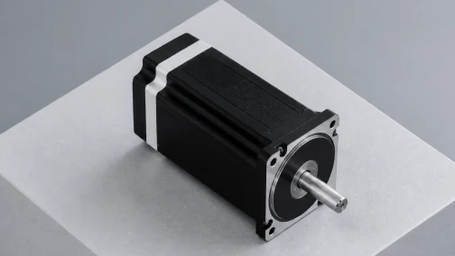

Engineering Fundamentals of Stepper Motor Microstepping
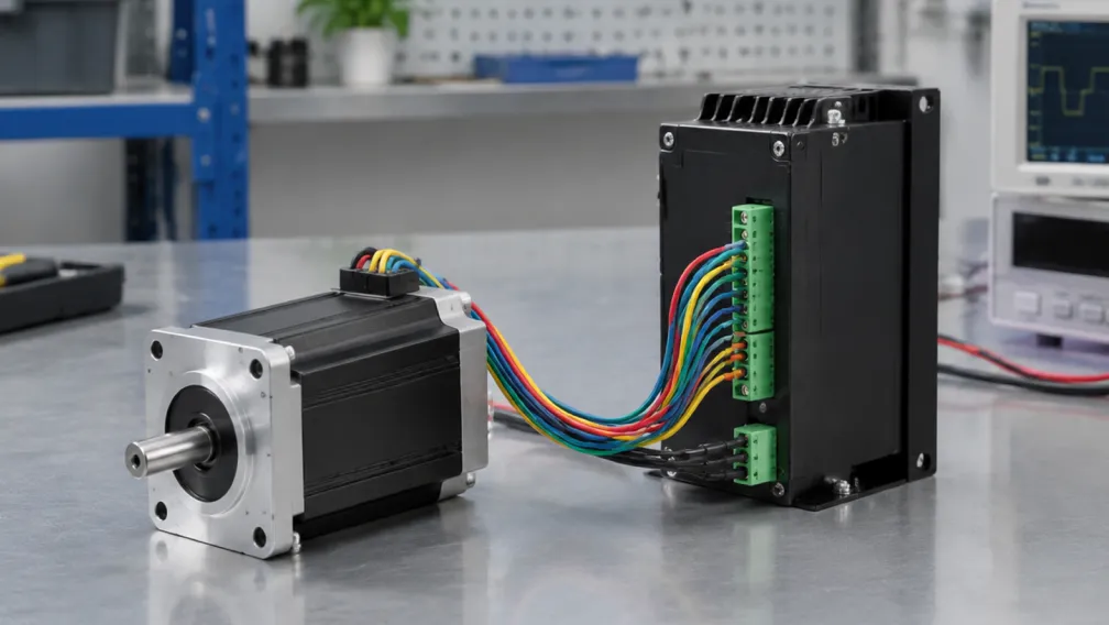
Microstepping is a driving technique used to increase the resolution of a stepper motor, reduce low-speed resonance, and provide smoother continuous motion. By proportioning the current between the two stator phases, a motor driver can position the rotor at intermediate locations between the mechanical full steps. Understanding the electrical mechanics, positional accuracy limits, and torque behavior of microstepping is necessary for configuring stable industrial motion control systems.
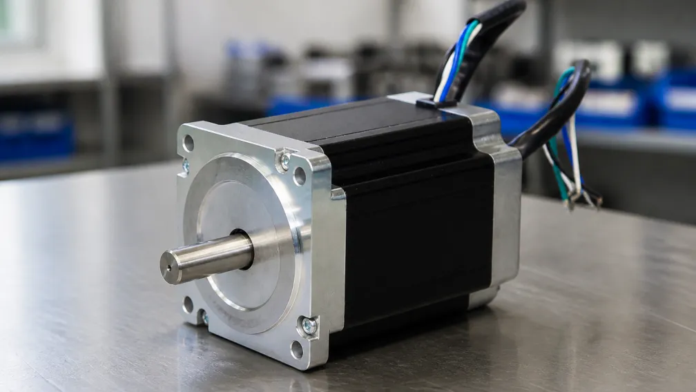
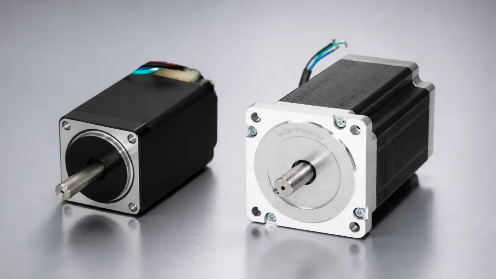
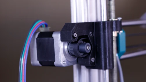
A standard 2-phase stepper motor features a mechanical step angle of 1.8 degrees, yielding 200 full steps per revolution. In full-step operation, the driver fully energizes either one or both phases in a discrete binary sequence. The rotor aligns with the strongest magnetic field, resulting in a distinct "jumping" motion from step to step. This discrete movement introduces vibration, particularly at low velocities where the step frequency matches the mechanical resonant frequency of the motor and load.
Microstepping resolves this by feeding continuous, digitally synthesized sine and cosine current waveforms into Phase A and Phase B. Instead of abruptly switching currents on or off, the motor driver scales the current incrementally. This forces the magnetic flux vector to rotate smoothly across the stator teeth, dragging the rotor along in sub-step increments. Common microstep resolutions range from half-stepping (400 steps/rev) to 1/256 stepping (51,200 steps/rev).
1. Resolution Limits and Positional Accuracy
Increasing the microstep setting proportionally increases the commanded resolution of the axis. A 1/16 microstep setting applied to a 1.8-degree motor divides each mechanical step into 16 discrete increments, creating a commanded step angle of 0.1125 degrees and requiring 3,200 pulses to complete one revolution.
| Microstep Divider | Pulses per Revolution (1.8° Motor) | Commanded Step Angle | Primary Engineering Benefit |
|---|---|---|---|
| Full Step (1/1) | 200 | 1.8000° | Maximum incremental torque, simple control |
| Half Step (1/2) | 400 | 0.9000° | Eliminates primary low-frequency resonance |
| 1/8 Step | 1,600 | 0.2250° | Excellent balance of smoothness and usable torque |
| 1/16 Step | 3,200 | 0.1125° | Industry standard for CNC and precision positioning |
| 1/64 Step | 12,800 | 0.0281° | Extreme acoustic noise reduction |
| 1/256 Step | 51,200 | 0.0070° | Requires highly specialized, high-frequency controllers |
Commanded resolution does not equate to mechanical accuracy. The physical construction of the motor imposes an absolute accuracy limit, typically rated at ±5% of a full step (±0.09 degrees for a 1.8-degree motor). This error is non-cumulative over multiple revolutions but means that sub-steps smaller than the mechanical tolerance may not result in immediate physical movement if external friction or load variations exceed the incremental torque.
2. Incremental Torque Degradation
Holding torque defines the motor's ability to maintain position when fully energized. Incremental torque defines the amount of rotational force generated by a single commanded microstep. As the microstep resolution increases, the incremental torque per sub-step drops significantly. This is a fundamental limitation of the electromagnetic relationship.
The incremental torque (T_inc) for a given microstep resolution can be approximated by the formula: T_inc = T_holding × sin(90° / N), where N is the microstep factor (e.g., 16 for 1/16 stepping).
For a motor with 2.0 Nm of holding torque configured for 1/16 microstepping, the torque generated to move a single sub-step is approximately 0.196 Nm. If the static friction (stiction) of the linear guide or leadscrew exceeds 0.196 Nm, the motor shaft will not move upon receiving the first pulse. The driver must receive subsequent pulses, increasing the phase current delta, until the accumulated torque exceeds the load resistance. This phenomenon manifests as following error in open-loop systems.
3. Mitigating Mechanical Resonance
Resonance occurs when the step pulse frequency aligns with the natural frequency of the rotor and the attached mechanical load. In full-step systems, the rotor overshoots and oscillates around the target position at the end of each step. This oscillation severely degrades torque and can cause the motor to stall abruptly.
Microstepping mitigates resonance by reducing the magnitude of each step. Because the phase current transitions smoothly along a sinusoidal curve, the magnetic flux changes gradually. The rotor is gently pulled to the next position rather than being subjected to a massive step-input of magnetic force. Operating at 1/8 or 1/16 microstepping effectively suppresses the primary low-speed resonance band (typically between 50 and 150 RPM) in industrial stepper motors. Higher microstep settings beyond 1/32 yield diminishing returns regarding resonance reduction.
4. Controller Frequency Requirements and Limitations
Configuring a high microstep resolution directly impacts the pulse frequency required from the motion controller. To rotate a motor at a specific velocity, the controller must output steps at a rate proportional to the microstep setting.
The required pulse frequency is calculated as: Frequency (Hz) = (RPM × Pulses per Revolution) / 60.
For a target speed of 1,000 RPM using a 1/16 microstep setting (3,200 pulses/rev), the controller must generate a stable 53.3 kHz pulse train. If the microstep setting is increased to 1/256 (51,200 pulses/rev), the same 1,000 RPM velocity requires a pulse frequency of 853.3 kHz. Standard PLC outputs and low-cost microcontrollers often max out at 100 kHz. Commanding frequencies beyond the hardware limit results in missed steps, software crashes, and unpredictable axis behavior.
5. Integration with Closed-Loop Stepper Systems
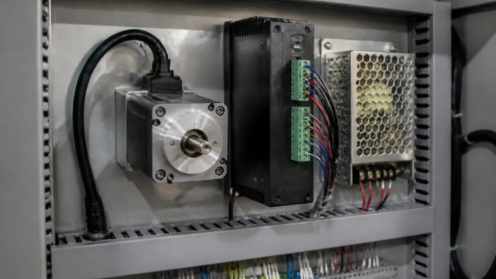
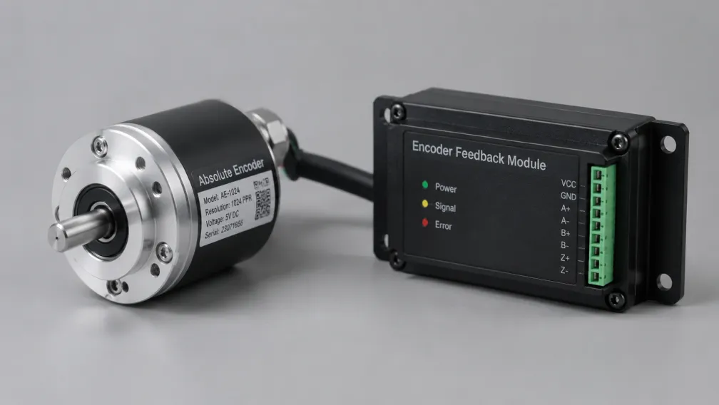
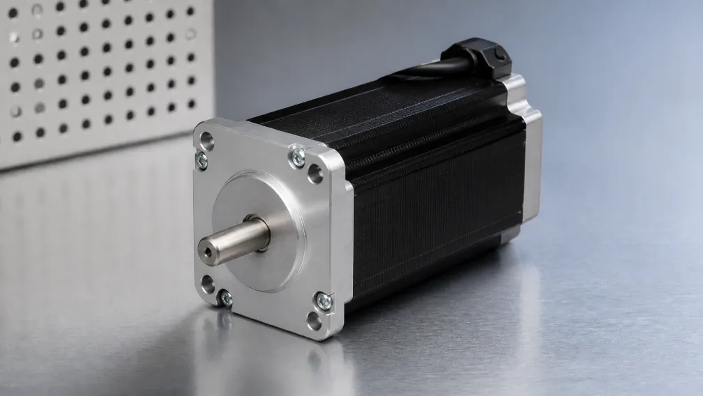
Applying microstepping to a closed loop stepper motor changes the fundamental operating paradigm. In a closed-loop system, an optical or magnetic encoder continuously monitors the actual shaft position. The driver uses this feedback to apply current vector control (similar to a servo drive) rather than blindly outputting open-loop microstep sine waves.
For these systems, the microstep setting on the driver primarily dictates the input command resolution required to match the encoder's internal resolution. If the motor features a 1,000-line encoder (4,000 counts per revolution after quadrature), setting the microstep driver to 4,000 pulses/rev ensures a 1:1 ratio between commanded pulses and encoder counts, simplifying the controller's scaling logic and preventing interpolation errors inside the drive's control loop.
6. OEM Configuration Checklist
When engineering an axis requiring high positional accuracy and smooth operation, utilize the following parameters to finalize the microstep configuration:
- Verify the motion controller's maximum reliable pulse output frequency.
- Calculate the required pulses per revolution based on mechanical transmission ratios (e.g., leadscrew pitch or pulley diameter).
- Select a microstep resolution that balances smooth low-speed operation (minimum 1/8 step) with the controller's maximum frequency.
- Ensure the incremental torque of the selected microstep setting exceeds the static friction of the unpowered mechanical assembly.
- If absolute positioning accuracy tighter than ±0.09 degrees is required, specify a closed-loop stepper system or a servo motor rather than relying solely on high microstep counts.
For detailed support on matching driver capabilities to specific motor frame sizes, consult the technical resources available through the Cymotorix download center. Engineering teams can also submit application specifications via the contact page for torque curve verification and optimal microstep recommendations.
Frequently Asked Questions (FAQ)
Question: Does increasing the microstep resolution increase the motor's holding torque?
Answer: No. The holding torque remains determined by the motor's physical construction and the maximum RMS current supplied by the driver. Microstepping affects positional increments and smoothness, not the maximum static holding force.
Question: Why does my stepper motor stall at high speeds when I use a high microstep setting?
Answer: High microstep settings require extremely high pulse frequencies from the controller to maintain high speeds. If the controller cannot generate clean, sharp pulses at that frequency, or if the driver's optocoupler inputs are too slow to register them, the driver misses steps and the motor stalls.
Question: What is the most practical microstep setting for general industrial automation?
Answer: A setting of 1/8 (1,600 pulses/rev) or 1/16 (3,200 pulses/rev) is standard. These settings provide sufficient resonance reduction and smooth motion without overwhelming standard PLC pulse outputs or sacrificing initial incremental torque.
Question: Can microstepping compensate for mechanical backlash in a gearbox or ballscrew?
Answer: No. Microstepping occurs entirely within the electromagnetic field of the motor. It cannot detect or correct for mechanical slop or backlash downstream of the motor shaft. Mechanical compensation requires an external linear encoder or precision-ground gearing.
Question: Is microstepping necessary if the motor is only operated at high speeds?
Answer: While microstepping's primary benefit is mitigating low-speed resonance, it also reduces audible noise and structural vibration across the entire speed range. Full-step operation is rarely recommended in modern equipment unless utilizing legacy hardware.
Question: How do I match the microstep setting to a closed-loop stepper driver?
Answer: Match the microstep setting to the quadrature count of the attached encoder. For example, use a setting of 4,000 pulses per revolution if the motor is equipped with a 1,000-line optical encoder. This simplifies tuning and position tracking.
-

Cymotorix
Stepper Motor & Servo Motor Manufacture
Cymotorix is a China-based motor manufacturer with 20+ years of experience producing hybrid stepper motors, AC servo motors, and matched drivers for OEM customers worldwide.