
The Engineering Purpose of Microstepping
Stepper motors natively operate in discrete mechanical increments. While this provides rigid open-loop positioning, it introduces vibration and coarse movement resolution. Microstepping is an electronic drive technique that divides these physical mechanical steps into smaller electrical sub-steps. However, engineers frequently conflate high microstep resolution with true mechanical positional accuracy, leading to stalled axes and failed machining tolerances.
Microstepping is primarily an acoustic and dynamic stabilization tool, not a method for achieving absolute sub-micron positioning on an open-loop axis. This technical manual defines the physics of sine/cosine current proportioning, the impact on mid-band resonance, the mathematical limits of incremental torque, and the engineering criteria for selecting the optimal microstep ratio for industrial machinery.
1. The Mechanical Baseline: Full-Step Commutation
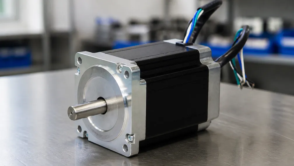
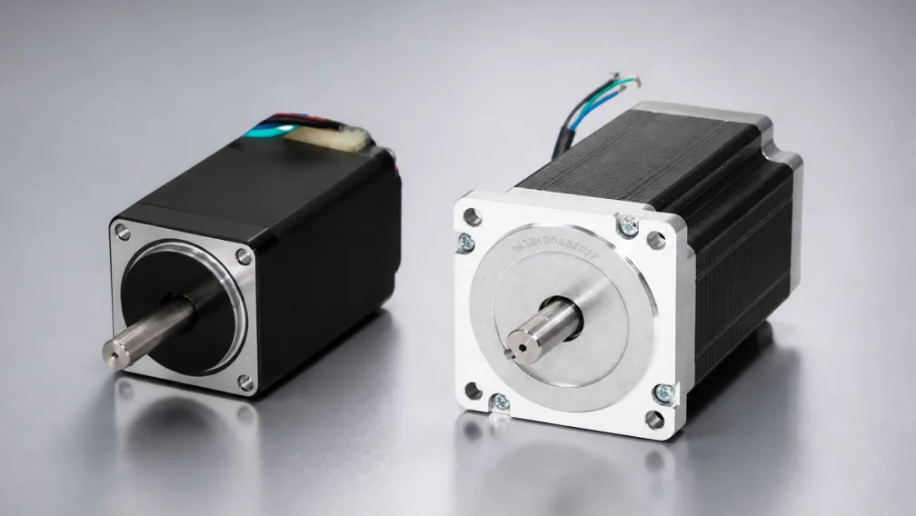
A standard 2-phase stepper motor features 200 physical teeth on its rotor and 8 magnetic poles on its stator, yielding a 1.8-degree physical step angle. In full-step mode, the drive applies maximum rated current to Phase A, then abruptly switches full current to Phase B. This snaps the rotor to the next magnetic detent with maximum force.
This square-wave commutation maximizes low-speed holding torque but generates maximum kinetic impact. The rotor overshoots the target tooth, gets pulled back, and rings before settling. This ringing creates severe low-frequency vibration, commonly known as mid-band resonance, which frequently causes open-loop systems to stall between 100 and 200 RPM.
2. The Physics of Sine/Cosine Current Proportioning
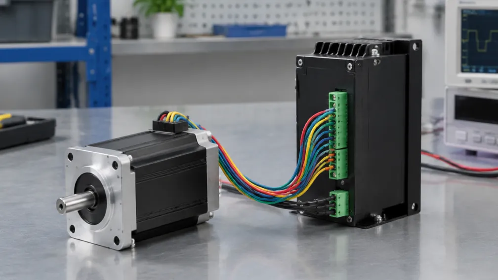
Microstepping replaces the abrupt square-wave current switching with a synthesized sine wave. Modern motor drivers utilize high-frequency Pulse Width Modulation (PWM) to continuously adjust the ratio of current flowing between Phase A and Phase B. By applying a sine wave to Phase A and a cosine wave to Phase B, the drive holds the rotor in magnetic equilibrium between the physical teeth.
Setting a digital drive to 1/8 microstepping creates 8 electrical sub-steps per physical step, resulting in 1,600 pulses per revolution (PPR). The rotor smoothly transitions from one sub-step to the next, drastically reducing the kinetic energy injected into the mechanical structure per pulse.
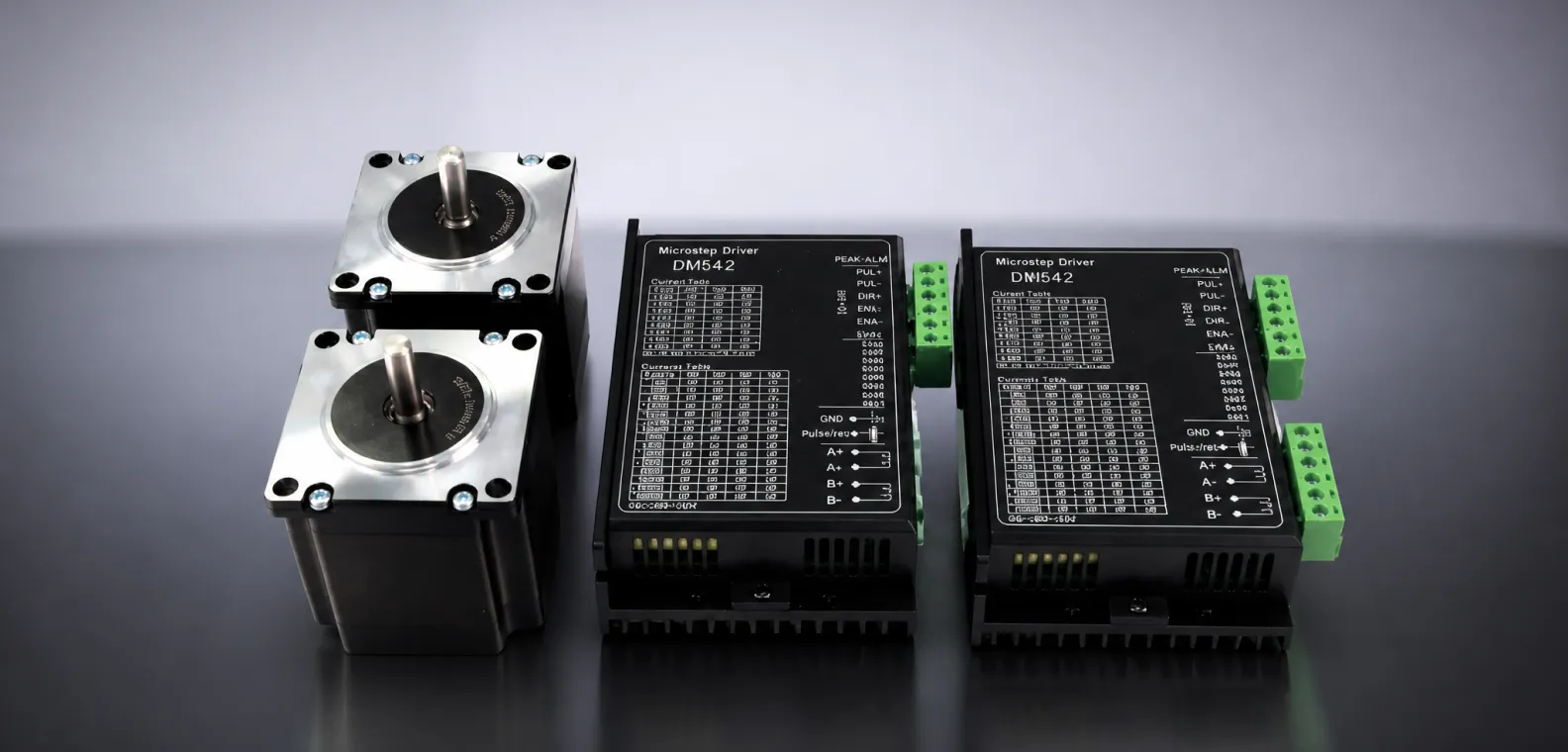
3. Acoustic Mitigation and Mid-Band Resonance Suppression
The primary engineering value of microstepping lies in its ability to suppress vibration. By breaking the 1.8-degree movement into smaller increments, the torque ripple across the axis is flattened. The rotor no longer experiences massive acceleration and deceleration spikes during each step transition.
This smooth energy transfer prevents the rotor from overshooting and ringing, effectively eliminating the mid-band resonance zone. In optical inspection systems, camera gantries, and medical fluid dispensing equipment, operating a drive at 1/16 or 1/32 microstepping is mathematically required to prevent the mechanical axis from blurring the camera exposure or agitating the fluid meniscus.
4. The Accuracy Fallacy: Resolution vs. Positional Accuracy
Increasing the drive setting to 256 microsteps (51,200 pulses per revolution) yields a theoretical resolution of 0.007 degrees per step. However, the motor's mechanical manufacturing tolerance (typically ±5% of a full step, or ±0.09 degrees) remains unchanged. Machining variations in the stator teeth, rotor concentricity, and bearing runout prevent the motor from physically hitting 51,200 distinct, repeatable positions.
While high microstep settings increase the smoothness of rotation, they do not increase absolute point-to-point accuracy. Once the microstep size falls below the motor's ±0.09-degree mechanical error threshold, the axis cannot guarantee exact positioning without external linear encoders verifying the payload location.
5. Incremental Torque Degradation at High Microstep Ratios
To execute a movement, the motor must generate enough incremental torque to overcome the static friction (stiction) of the mechanical load. The incremental torque per microstep drops drastically as the microstep ratio increases. The incremental torque for a microstep is calculated as the full-step holding torque multiplied by the sine of the step angle.
At 1/16 microstepping, the incremental torque generated by a single pulse is less than 10% of the motor's rated full-step torque. If the load friction exceeds this small incremental force, the motor will not physically move when the first pulse arrives. The controller must send several consecutive microstep pulses before the electrical current imbalance generates enough torque to break friction, causing the axis to suddenly "jump" into position. This phenomenon creates severe tracking lag in high-resolution CNC contouring.
6. Engineering Selection: Calculating the Optimal Microstep Ratio
Question: How do engineers determine the optimal microstepping ratio for an industrial motion axis to balance smoothness against torque degradation?
Answer: Engineers standardize on ratios of 1/8 (1,600 PPR) or 1/16 (3,200 PPR). These ratios eliminate 95% of mechanical resonance and torque ripple without overwhelming the controller's optocoupler bandwidth. Ratios exceeding 1/32 provide no additional physical accuracy due to the motor's native machining tolerances, and the drastically reduced incremental torque increases the risk of positioning lag against static friction.
7. Overcoming Limitations with Closed-Loop Feedback
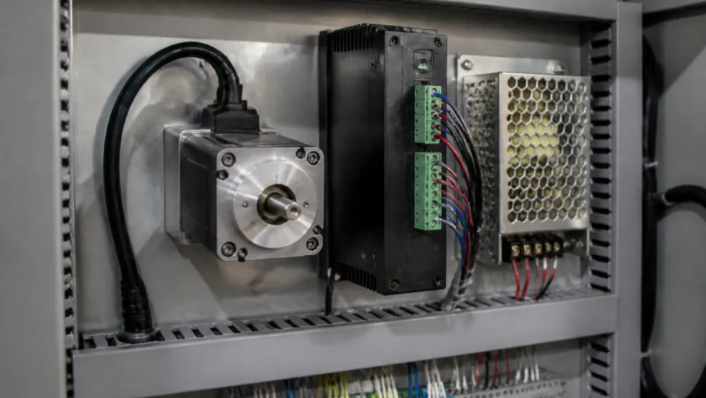
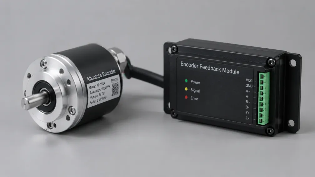
When an application demands both extreme acoustic smoothness and verified sub-degree positional accuracy, manipulating open-loop microstepping is insufficient. Engineers must transition the axis to a closed loop stepper motor. By integrating an absolute or incremental encoder, the drive verifies the true mechanical coordinate in real time.
A closed-loop drive executing Field-Oriented Control (FOC) ignores the physical detent limitations of the stator teeth. It dynamically shifts the current vector to force the rotor into the exact commanded position, automatically compensating for internal manufacturing tolerances, thermal expansion, and mechanical friction. This delivers the vibration-free performance of high microstepping combined with absolute positional certainty.
Engineering Support and Drive Integration
Selecting the correct drive parameters requires analyzing the friction profile, pulse bandwidth, and accuracy tolerances of the mechanical load. Cymotorix engineers a complete ecosystem of digital motor drivers featuring advanced microstep emulation, which interpolates low-frequency PLC pulse trains into ultra-smooth 256-microstep sinusoidal waveforms. Our engineering team provides direct support for calculating resonance frequencies and sizing closed-loop feedback systems. Access wiring diagrams and technical parameter sheets via our download center, or contact our application engineering department to specify the optimal actuation architecture for your machinery.
Frequently Asked Questions (FAQ)
Question: Does increasing the microstep resolution reduce the total holding torque of the stepper motor?
Answer: No. The absolute holding torque at the native full-step and half-step positions remains exactly the same. However, the incremental torque required to move from one microstep to the adjacent microstep is drastically reduced, which can cause positioning lag against high static friction.
Question: Why does my motor lose torque and stall at high speeds when set to 1/128 microstepping?
Answer: At high speeds and high microstep resolutions, the required pulse frequency from the machine controller exceeds the physical bandwidth of the driver's optocoupler inputs. The drive begins dropping high-frequency pulses, which desynchronizes the commutation and causes an immediate stall.
Question: Can microstepping fix a stepper motor that stalls during rapid acceleration?
Answer: If the stall is caused by mid-band resonance (vibration), microstepping will fix it by smoothing the kinetic energy transfer. If the stall is caused by a lack of raw acceleration torque to overcome the payload inertia, microstepping will not help; the system requires a larger motor, a gearbox, or a higher bus voltage.
Question: What is microstep emulation in modern digital stepper drives?
Answer: Microstep emulation is a drive-level firmware feature. It takes a low-resolution input signal (like full step or half step) from a standard PLC and internally interpolates it into a high-resolution 256-microstep waveform. This gives the motor the acoustic smoothness of high microstepping without requiring high-frequency pulse output hardware from the controller.
Question: Is a 1.8-degree motor running at 1/2 microstepping mechanically identical to a 0.9-degree motor running at full step?
Answer: Electrically yes, but mechanically no. The 0.9-degree motor has double the physical rotor teeth, providing higher native magnetic stiffness and accuracy at those specific physical positions. The 1.8-degree motor relies entirely on perfect electrical current balancing to hold the half-step position, making it more susceptible to load deflection.
Question: How do I calculate the required pulse frequency for a specific microstep setting?
Answer: Multiply the motor's native steps per revolution by the microstep multiplier, then multiply by the target RPM, and divide by 60. For example, to run a standard motor (200 steps) at 16 microsteps and 600 RPM, the calculation is: (200 × 16 × 600) / 60 = 32,000 Hz (32 kHz). Ensure your controller can output this frequency.
-

Cymotorix
Stepper Motor & Servo Motor Manufacture
Cymotorix is a China-based motor manufacturer with 20+ years of experience producing hybrid stepper motors, AC servo motors, and matched drivers for OEM customers worldwide.