
Introduction to the CNC Motion Dilemma: Bandwidth vs. Cost Efficiency
When engineering high-precision CNC machinery—whether it is a multi-axis gantry mill, a high-speed fiber laser cutter, or a production-grade lathe—the choice of the axis actuation ecosystem represents one of the most critical design decisions. Historically, machine designers faced a polarized selection: inexpensive, simple open-loop stepper systems that lacked positional verification, or premium AC servo platforms offering extreme performance but requiring complex tuning frameworks and a significant capital premium. The introduction of digital closed-loop stepper systems has blurred these boundaries, creating a mid-tier control architecture that challenges traditional paradigms.
Selecting the wrong actuation setup results in immediate operational bottlenecks, including structural finish defects caused by axis lag, positioning errors due to compliance, or excessive thermal generation that distorts the mechanical alignment of the machine lead screws. This application manual establishes a rigorous, quantitative framework comparing high-torque closed-loop step networks against high-bandwidth AC servo systems. By evaluating magnetic pole physics, nested control loops, torque-to-inertia ratios, and dynamic speed regulation windows, engineers can accurately align their motion profiles with empirical system demands.
1. Rotor Geometry and Pole-Count Physics: The Foundation of Torque Profiles
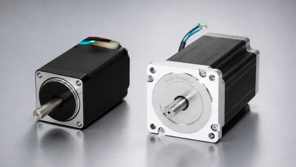
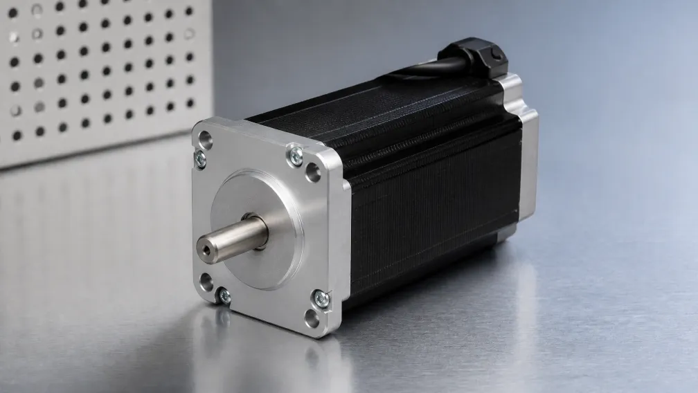
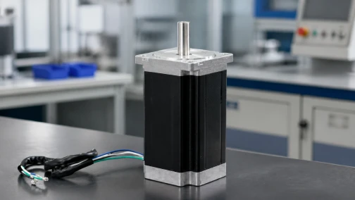
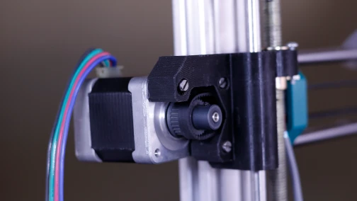
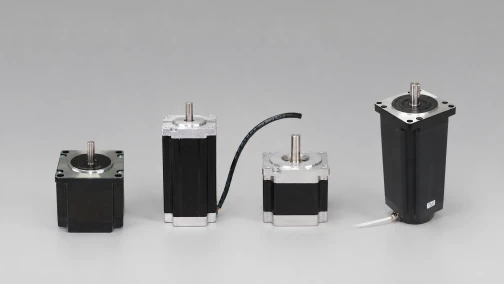
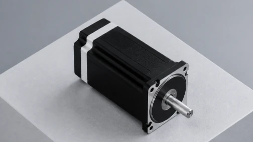
The primary operational differences between closed-loop steppers and AC servos originate from the physical geometry of their internal rotors and the pole count of their stators. A standard hybrid stepper motors configuration is a high-pole system, typically engineered with 50 distinct magnetic poles mapped across a 2-phase or 3-phase stator arrangement. This architectural choice yields 200 physical full steps per single 360-degree rotation, meaning the rotor naturally moves in small, rigid 1.8-degree increments. Because the magnetic poles are spaced closely together, the motor develops exceptional magnetic holding torque at zero velocity and low rotational speeds, since a minor angular deflection generates an immediate, aggressive electromagnetic restoring force.
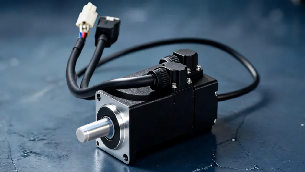
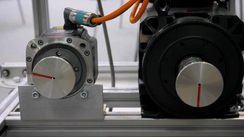
Conversely, a brushless AC servo motor is inherently a low-pole architecture, generally containing between 4 and 8 permanent magnet poles bonded directly to a low-inertia shaft. Because the physical steps do not exist, a servo cannot operate without continuous electronic commutation governed by high-resolution feedback. At low speeds, the low pole count means the servo cannot rely on natural magnetic holding stiffness; instead, it relies entirely on its drive electronics to calculate and supply the exact phase current vectors required to hold an angular position. However, this low pole count becomes a massive advantage as rotational velocity escalates. While the high inductive frequency of a 50-pole stepper creates severe impedance that starves phase current at high speeds, the low-pole servo motor maintains clean current pathways, allowing it to rev smoothly up to 3,000 or 5,000 RPM with flat torque retention.
2. Control Loop Architecture: Step Tracking vs. Nested 3-Loop Field-Oriented Control
The term "closed-loop" is applied to both platforms, yet their underlying signal-processing pathways and update rates are fundamentally distinct. A modern closed-loop stepper motor drive tracks a command trajectory using an optical or magnetic encoder (typically ranging from 1,000 to 4,000 pulses per revolution). The drive executes a Field-Oriented Control (FOC) algorithm where the current vector is shifted based on encoder feedback to eliminate the possibility of missed steps. If a high cutting load causes the rotor to lag behind the command pulse stream, the internal drive controller increases phase current to clear the error. However, it remains a step-and-direction tracker at its core; it views position deviation primarily as an error to be corrected by altering current magnitude within the existing step target boundary.
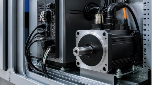
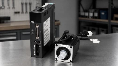
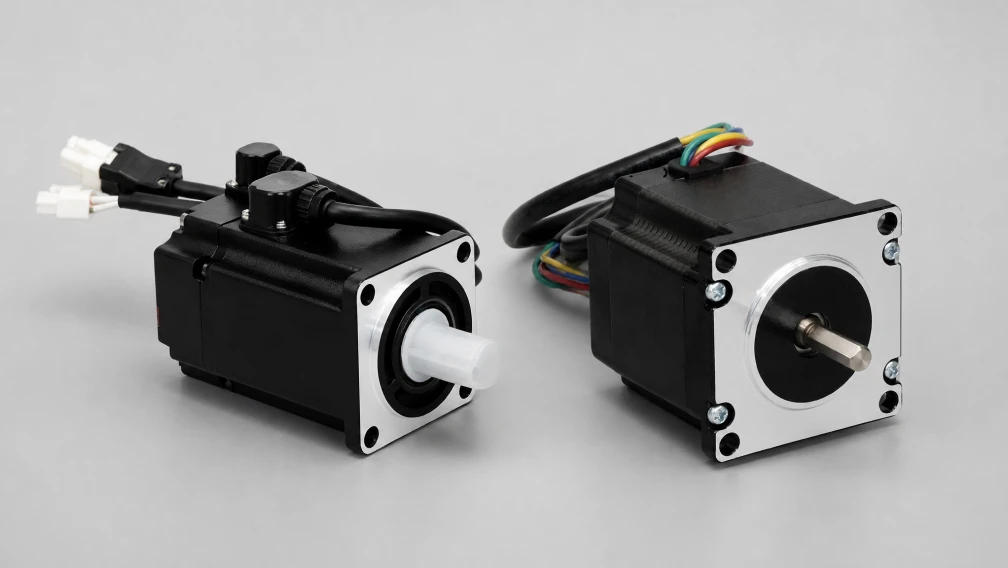
An advanced AC servo platform, driven by sophisticated rs3 servo drive electronics, deploys three fully nested, independent PID (Proportional-Integral-Derivative) control loops running in tight synchronization. The innermost loop is the current (torque) loop, updating at frequencies up to 20 kHz or 32 kHz to manage vector space modulation. Wrapped around this is the velocity loop, checking rotor speed against command trajectories at 4 kHz to 8 kHz. The outermost ring is the position loop, which relies on absolute or incremental encoders with extremely high resolutions (often 20-bit to 24-bit, delivering over 16 million counts per revolution). This nested architecture means the servo drive does not wait for a step error to accumulate; it actively predicts mechanical lag, compensates for load inertia variations in real time, and dynamically alters torque delivery within microseconds to maintain perfect alignment with the motion controller's interpolation profile.
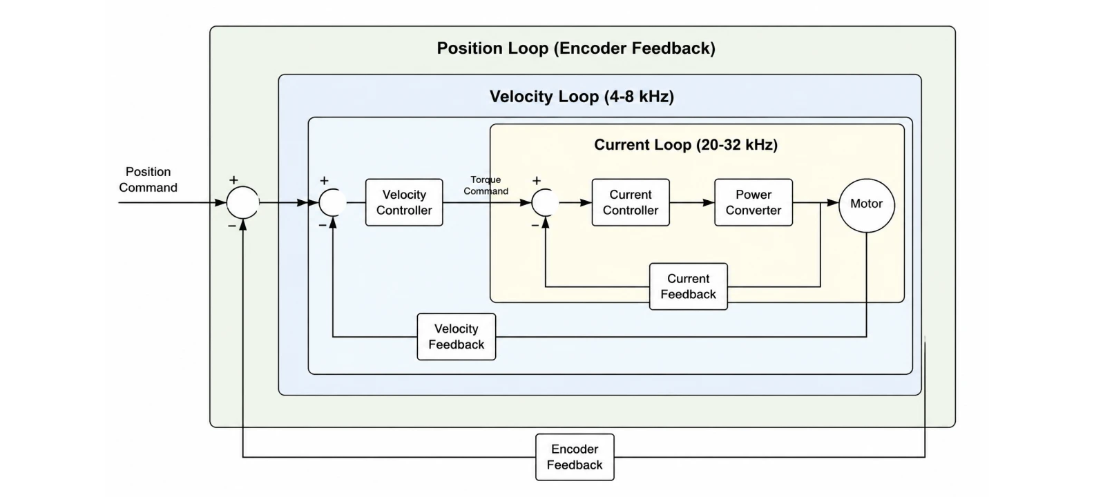
3. Comprehensive Technical Comparison Matrix
The matrix below outlines the critical mechanical and electrical boundaries separating these two industrial movement methodologies:
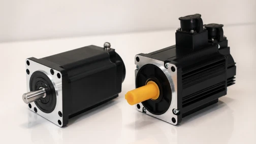
| Performance Parameter | Closed-Loop Stepper System | Brushless AC Servo System |
|---|---|---|
| Physical Pole Count | 50 Poles (High Pole Density) | 4 to 8 Poles (Low Pole Density) |
| Optimal Speed Window | 0 to 600 RPM (Drops sharply past 1,000 RPM) | 0 to 3,000+ RPM (Continuous flat curve) |
| Feedback Resolution | 1,000 to 4,000 PPR (Pulses Per Rev) | 20-bit to 24-bit Absolute (Up to 16M+ counts) |
| Settling Time Profile | Near-zero at low speeds (Rigid position hold) | Determined by PID tuning (Requires settling window) |
| Position Hunting at Rest | Absolute zero (Dead-still deadband lock) | Minor dithering (+/- 1 encoder count via PID) |
| Inertia Matching Window | Forgiving (Handles up to 30:1 load mismatches) | Strict (Prefers 5:1 to 10:1 mismatch max) |
| Relative System Cost | Baseline (Highly cost-effective) | 2x to 3x premium over closed-loop step setups |
4. Torque-Speed Dynamics and Acceleration Envelopes
To maximize the throughput of a CNC machine toolpath, engineers must design around the dynamic torque equation: T_total = T_inertia + T_friction + T_process, where T_inertia is direct rotor-load acceleration torque (T_inertia = J * alpha). The acceleration rate (alpha) a motor can deliver is strictly bounded by its torque-speed curve. A 2-phase stepper motor operating in a closed-loop configuration provides exceptional low-speed torque that frequently outclasses a servo motor of equivalent frame size. Below 300 RPM, the stepper can snap an axis into motion almost instantaneously. However, as velocity climbs, inductive reactance (X_L = 2 * pi * f * L) climbs linearly with the switching frequency (f). This impedance starves the winding circuit of current, causing the available torque to decay exponentially. By the time a closed-loop step system reaches 1,200 RPM, its torque output has often dropped by 60% to 80% of its nominal rating, rendering it incapable of sustaining high-velocity material removal.
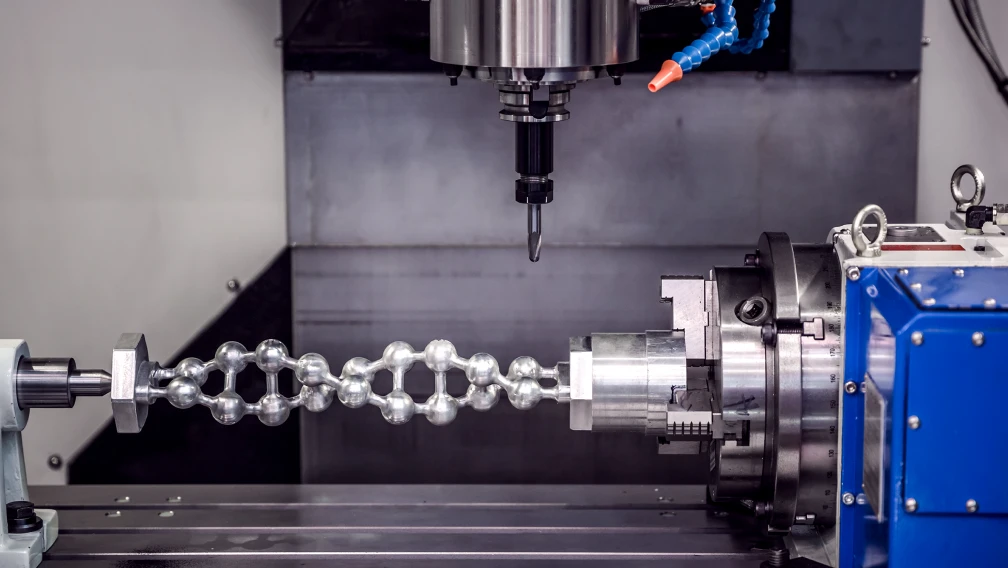
An AC servo motor exhibits a radically different torque profile, characterized by a completely flat continuous torque output up to its rated speed (typically 3,000 RPM), with an extended intermittent peak torque zone. Modern servo systems can deliver a peak torque of 300% of their rated continuous value during short acceleration windows. This capability allows a servo-driven CNC axis to sustain aggressive acceleration profiles (exceeding 1G to 2G) throughout its entire speed range. If a CNC gantry requires rapid-travel velocities exceeding 15 meters per minute combined with heavy high-feed milling cuts, the flat torque envelope of an AC servo is mathematically required to prevent tracking error faults and tool path distortion.
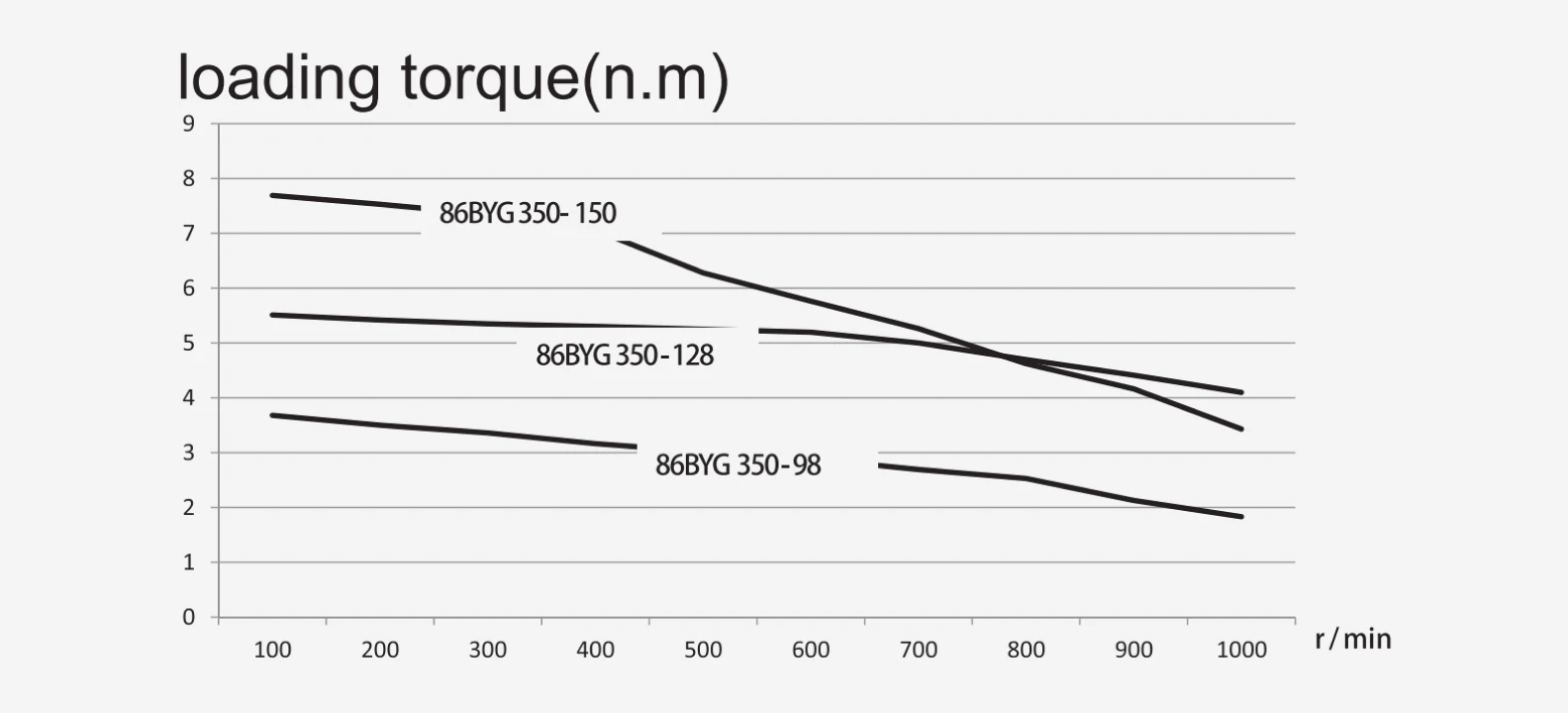
5. Settling Time, Compliance, and Standstill Behavior
In high-speed CNC drilling, pick-and-place indexing, or fine engraving, the behavior of the axis when coming to a dead stop is just as critical as its high-speed travel. Closed-loop stepper systems display a distinct advantage regarding settling time in low-inertia configurations. Because their high-pole count creates natural mechanical detent alignment points, when a stepper finishes a movement command, it locks into the target position with zero hunting and near-zero settling time. The motor remains dead-still at standstill, making it ideal for applications like laser scanning or additive manufacturing where minor positional dithering ruins the material state.
An AC servo motor is always dynamically active. Because it relies on an error-driven PID loop, when it reaches a target coordinate, it continuously calculates corrections based on its high-resolution encoder readings. This introduces a measurable settling time parameter, where the motor shaft oscillates slightly within a microscopic window (+/- 1 encoder count) as the integral term zeroes out the remaining tracking error. Furthermore, if a servo system is tuned with insufficient gains, or if the load-to-rotor inertia mismatch exceeds design limits, the motor will exhibit audible "hunting" or dithering at standstill. This compliance requires meticulous mechanical layout configurations, including low-backlash planetary gearboxes or precision ball screws, paired with rigorous loop tuning to guarantee that the settling window does not impact total machine cycle times.
6. Strategic Application Mapping: Making the Technical Selection
The engineering decision between these two motion platforms must be guided by clear operational metrics rather than simply choosing the most expensive hardware. Below are the definitive engineering guidelines for deploying these systems across industrial CNC designs:
- Deploy Closed-Loop Stepper Platforms When: The maximum required axis velocity remains safely below 800 RPM; the mechanical transmission relies on high-reduction ball screws or lead screws that convert moderate motor speeds into sufficient linear thrust; the system demands absolute standstill stability with zero position dithering; and the project budget requires premium reliability without the 3x cost penalty of a servo network. Typical applications include mid-size CNC routers, plasma cutting tables, industrial 3D printers, automated dosing axes, and lab automation gantries.
- Deploy Brushless AC Servo Platforms When: The axis design demands rapid-travel speeds exceeding 1,000 RPM at the motor shaft (e.g., direct-drive rack-and-pinion installations or high-lead ball screws); the toolpath profile requires extreme acceleration and deceleration ramps to clear intricate 3D geometries without corner rounding; the cutting forces vary dynamically in a wide envelope, requiring real-time torque adaptation; and the machine requires seamless integration with multi-axis CNC controllers via high-speed industrial Ethernet protocols. Typical applications include high-precision vertical machining centers (VMCs), production turning centers, high-speed fiber laser cutters, and advanced multi-axis packaging machinery.
If you need assistance analyzing your machine's torque and speed requirements, contact our engineering team for a detailed motion control review.
Frequently Asked Questions (FAQ)
Question: Does a closed-loop stepper motor eliminate the risk of missing steps entirely?
Answer: Yes. A closed-loop stepper drive utilizes encoder feedback to continuously monitor the actual physical position of the rotor relative to the commanded step sequence. If an unexpected external resistance causes the rotor to lag, the drive immediately modulates the phase current vector and magnitude to correct the error in real time. If the overload condition persists and cannot be cleared within a preconfigured tracking window, the drive will instantly trip an alarm fault signal to stop the entire CNC controller, preventing the machine from ruining raw material.
Question: Why do AC servo motors require a complex mechanical tuning process while closed-loop steppers do not?
Answer: Because a closed-loop stepper has a high physical pole count (50 poles), it possesses inherent mechanical stiffness that locks the rotor into position naturally. An AC servo has very few poles (4 to 8) and is completely dependent on its drive software to maintain position via active calculation. The drive's PID loop must be finely calibrated to match the specific mass and inertia of the physical CNC axis. Incorrect tuning parameters cause the servo to either oscillate violently or respond sluggishly, whereas a closed-loop stepper drive functions reliably out of the box across a broad range of load ratios.
Question: What is positional "hunting" at standstill, and which system suffers from it?
Answer: Standstill hunting, or dithering, is a phenomenon where a motor shaft makes continuous, microscopic adjustments back and forth while attempting to maintain a fixed position. This behavior occurs in AC servo systems because their control loops are constantly calculating correction errors based on high-resolution encoder data. Closed-loop steppers do not suffer from hunting; they utilize their high pole density to lock rigidly into a fixed deadband coordinate, remaining completely motionless when at rest.
Question: Can I replace an existing open-loop stepper with a closed-loop stepper without changing my CNC controller?
Answer: In almost all cases, yes. Standard digital closed-loop stepper drives accept the exact same Step and Direction (Pulse/DIR) signals used by traditional open-loop stepper controllers. Since the encoder wiring runs directly between the motor housing and its dedicated closed-loop drive rather than back to the main CNC controller, the entire system looks exactly like a standard stepper axis to your existing control interface, making it a simple drop-in upgrade.
Question: How does the load-to-rotor inertia ratio impact the selection of these motion systems?
Answer: The load-to-rotor inertia ratio measures the mechanical resistance of your moving axis relative to the internal inertia of the motor shaft. AC servo motors feature low internal rotor inertia to allow for high-speed performance, meaning they are sensitive to large mass mismatches and typically require an inertia ratio below 10:1 to maintain tuning stability. Closed-loop steppers have massive, high-inertia rotors that are highly forgiving, allowing them to handle load inertia mismatches up to 30:1 or higher without inducing loop oscillation or feedback errors.
Question: Which system provides superior surface finish quality during complex 3D contour milling?
Answer: AC servo platforms provide superior surface finish profiles during dynamic multi-axis CNC milling path execution. Because a servo drive utilizes continuous high-resolution nested loops with update frequencies in the kilohertz range, it responds smoothly to changing tool pressures and maintains perfect alignment with the controller's interpolation path. Closed-loop steppers, while highly accurate, can introduce minor velocity ripple at specific low speeds due to their discrete pole-to-pole transitions, which can manifest as subtle harmonic patterns on highly polished mold or die surfaces.
-

Cymotorix
Stepper Motor & Servo Motor Manufacture
Cymotorix is a China-based motor manufacturer with 20+ years of experience producing hybrid stepper motors, AC servo motors, and matched drivers for OEM customers worldwide.