
Why Wiring Errors Are the Most Common Commissioning Failure
A stepper motor that vibrates without rotating, overheats at standstill, or stalls at moderate speed is wired incorrectly more often than it is defective. The motor's external lead count reflects its internal winding arrangement, and each arrangement imposes specific requirements on the driver, the current setting, and the achievable speed. Getting the wiring right is a fifteen-minute job with a multimeter; getting it wrong produces failure modes that look exactly like a bad motor or a bad driver, which is why wiring verification belongs at the start of every troubleshooting session.
This guide explains the three lead configurations used in industrial hybrid 2-phase stepper motors, how to identify windings with a multimeter, how series and parallel connections change motor behavior, and the connection mistakes that damage equipment.
1. What the Lead Count Tells You About the Windings Inside
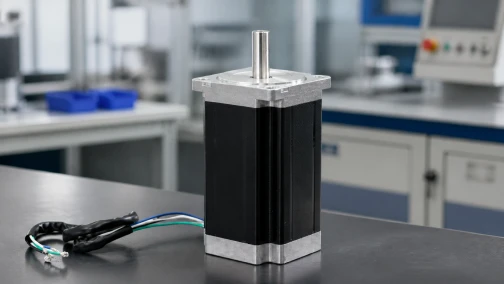
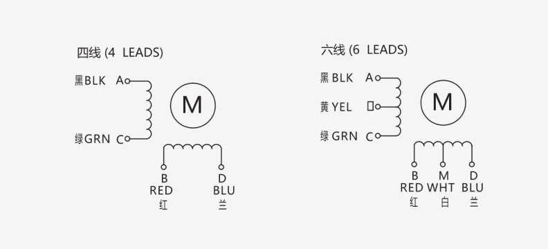
A standard 2-phase hybrid stepper contains two independent stator windings, Phase A and Phase B. The number of leads exiting the housing depends on how many connection points the manufacturer brought out:
| Lead Count | Internal Arrangement | Drive Modes Available | Typical Use |
| 4 leads | Two coils, both ends exposed, no center taps | Bipolar only | Modern industrial standard; highest torque per amp |
| 6 leads | Two coils with a center tap on each | Unipolar, bipolar full-coil, bipolar half-coil | Legacy systems, simple unipolar drivers |
| 8 leads | Four independent half-windings | Bipolar series or bipolar parallel | Applications needing speed or torque reconfiguration |
The 4-lead motor is the modern default because the bipolar chopper drive became standard. Unipolar drives survived in legacy equipment because they never reverse current direction and need simpler electronics, but they energize only half of each winding at a time, which gives up roughly 30% of the torque the copper can produce. The 8-lead motor exists for flexibility: one motor can be optimized for low-speed torque or high-speed output by changing how its half-windings are joined.
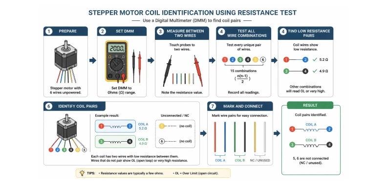
2. Identifying Windings With a Multimeter
Wire color codes vary between manufacturers, so never trust colors alone. Identification takes two measurements:
- Finding coil pairs. Set the multimeter to resistance. Wires belonging to the same winding show low resistance between them, typically 1 to 10 ohms depending on motor size. Wires on different windings show an open circuit. On a 4-lead motor this test alone completes the identification.
- Finding center taps. On a 6-lead motor, the center tap reads half the end-to-end resistance to either end of its coil. If a full coil measures 4 ohms end to end, the center tap measures 2 ohms to each end. The two wires reading the full value are the coil ends.
- No meter at hand. Spin the shaft by hand, then short two wires together and spin again. If the shaft suddenly resists, those two wires terminate the same winding. The shorted winding acts as a generator loaded by its own leads.
Record the result before connecting anything. The driver terminals only need to know which two wires form Phase A and which form Phase B; the polarity within a pair decides rotation direction and can be corrected later.
3. Wiring a 4-Lead Bipolar Motor
The 4-lead connection is the simplest and the most common in industrial equipment. Connect one winding to the driver's A+ and A− terminals and the other to B+ and B−. Set the drive current to the motor's rated phase current. Two properties define this configuration: the full winding is always in circuit, so torque per amp is the highest of any arrangement, and winding inductance is fixed by the manufacturer, so high-speed torque depends on the supply voltage rather than on wiring choices. If high-speed performance is marginal, the lever is a higher supply voltage within the drive's rating, following the V ≈ 32 × √L guideline covered in our stepper motor sizing guide.
4. Wiring a 6-Lead Motor: Three Options, One Clear Winner
The 6-lead motor offers three usable configurations:
Unipolar mode connects both center taps to the positive supply and switches the four coil ends to ground. It needs only a simple transistor array as the driver, but uses half of each winding at any moment, so torque and efficiency suffer. It survives in cost-driven consumer equipment and legacy panels.
Bipolar full-coil mode leaves the center taps disconnected and connects the four coil ends to a bipolar drive. The entire winding is energized, inductance is at its maximum, and the motor delivers its best low-speed torque at the cost of a lower speed ceiling.
Bipolar half-coil mode uses one coil end and the center tap, cutting the active turns in half. Inductance drops to roughly a quarter of the full-coil value, current can rise faster, and high-speed torque improves, while low-speed torque falls by about 30% against the full-coil connection at the same current.
For any machine driven by a modern bipolar chopper drive, full-coil bipolar is the correct default. Use half-coil only when the axis specifically needs more speed from an existing motor.
5. Wiring an 8-Lead Motor: Series or Parallel
The 8-lead motor forces a real engineering decision. Joining the two half-windings of each phase in series or in parallel produces two electrically different motors from the same hardware:
| Parameter | Series Connection | Parallel Connection |
| Winding inductance | 4× the parallel value | Baseline (lowest) |
| Drive current setting | Rated current per half-winding | 2× the per-winding rating |
| Low-speed torque | Maximum | Equal at same copper loss |
| High-speed torque | Falls early | Held to much higher RPM |
| Best fit | Low-speed, high-torque axes | High-feedrate gantries, routing axes |
The series connection quadruples inductance because turns double and inductance scales with turns squared. High inductance slows current rise, so torque decays early with speed. The parallel connection keeps inductance low and preserves torque deep into the speed range, but the drive must deliver the combined current of both half-windings, typically twice the series rating. Confirm the stepper driver can supply that current before committing to parallel. When one motor model serves both slow and fast machine variants, the 8-lead arrangement lets the same part number cover both, which simplifies spares and purchasing.
6. Connection Mistakes That Damage Equipment
Five wiring errors account for most field failures:
- Crossed coil pairs. Connecting one wire of Phase A and one of Phase B to the same driver channel makes the motor fight itself: it vibrates, buzzes, and never rotates. Re-check pairs with the multimeter before assuming a drive fault.
- Disconnecting under power. Unplugging a motor lead while the drive is energized produces a back-EMF spike that can destroy the drive's output stage instantly. Power down or disable the drive before touching motor wiring.
- Current set for the wrong configuration. An 8-lead motor rewired from series to parallel but left at the series current setting runs at half its intended current and loses torque everywhere; set the other way, it overheats. The current setting belongs to the wiring configuration, not to the motor alone.
- Reversing direction in software by guessing. If the motor turns the wrong way, swap the two wires of one phase, either A+ with A− or B+ with B−. This is the correct hardware fix and it never risks a mis-phased connection.
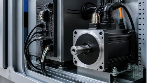
- Motor cables routed with signal wiring. Phase cables carry switched current and radiate EMI. Keep them away from encoder, sensor, and communication lines, use twisted pairs, and ground the cable shield at the drive end in electrically noisy cabinets.
7. When Wiring Is Correct but Performance Is Still Wrong
Correct wiring establishes the electrical baseline; it cannot compensate for a mismatched system. A motor that stalls despite correct wiring and current settings is usually undersized for the load or running inside its resonance band, and the diagnostic sequence in our noise and vibration guide applies. An axis that cannot tolerate any risk of undetected step loss belongs on closed-loop stepper motors, which add encoder feedback while keeping the same wiring and pulse interface.
Need a Wiring Diagram for Your Specific Motor?
Every motor we ship includes a wiring diagram, and the full datasheet library with dimension drawings and CAD models is in our download center. For custom lead configurations, connectors, or cable lengths, contact our engineering team; we configure lead exits, JST or Molex terminals, and cable assemblies to your drawing.
Frequently Asked Questions (FAQ)
Question: What is the difference between a 4-wire and a 6-wire stepper motor?
Answer: A 4-wire motor has two independent windings with both ends brought out and runs only in bipolar mode with a bipolar drive. A 6-wire motor adds a center tap to each winding, which allows unipolar operation with simple drivers, or bipolar operation by ignoring the taps. The 6-wire motor is more flexible, but a 4-wire motor driven bipolar delivers the highest torque per amp because its full winding is always energized.
Question: Can I use a 6-wire stepper motor with a bipolar driver?
Answer: Yes. Leave both center tap wires disconnected and insulated, and connect the four coil-end wires to the bipolar drive exactly like a 4-wire motor. This full-coil bipolar connection gives the best low-speed torque. Alternatively, using one coil end and the center tap halves the active turns, which improves high-speed torque at the cost of roughly 30% of low-speed torque.
Question: Should I wire an 8-lead stepper motor in series or parallel?
Answer: Choose series for low-speed, high-torque axes where the motor rarely exceeds a few hundred RPM, since the higher inductance is harmless at low step rates. Choose parallel for high-feedrate axes, because inductance drops to a quarter of the series value and torque holds to much higher RPM. Parallel mode requires the drive to supply twice the per-winding rated current, so verify the drive's current capacity first.
Question: Why does my stepper motor vibrate and buzz but not rotate?
Answer: The most common cause is a crossed coil connection: one wire from each phase landed on the same driver channel, so the windings fight each other. Identify the two winding pairs with a multimeter and reconnect them correctly. If the pairs are correct, check that the drive receives a clean pulse signal and that the current setting is not near zero.
Question: Does the wiring configuration affect motor torque?
Answer: Yes, at speed. At standstill, series and parallel connections on an 8-lead motor produce the same torque at equal copper loss. As speed rises, the high-inductance series connection cannot build current fast enough and torque falls early, while the parallel connection holds torque to much higher RPM. Unipolar drive of a 6-lead motor sacrifices about 30% of available torque at all speeds because only half of each winding is energized.
Question: Can I extend the cable between the motor and the driver?
Answer: Yes, within limits. Use cable with adequate conductor gauge for the phase current, keep runs as short as practical, and use twisted pairs for each winding. Long or undersized cables add resistance and inductance that reduce high-speed torque marginally, and poorly shielded long runs inject noise into nearby signal wiring. For runs beyond a few meters or in electrically noisy environments, use shielded cable grounded at the drive end.
Question: How do I reverse the rotation direction of a stepper motor?
Answer: Either invert the direction signal at the controller, or swap the two wires of one motor phase at the driver terminals. Both methods are equally valid. Never swap wires between phases, and always power down the drive before changing motor wiring to avoid back-EMF damage to the output stage.
-

Cymotorix
Stepper Motor & Servo Motor Manufacture
Cymotorix is a China-based motor manufacturer with 20+ years of experience producing hybrid stepper motors, AC servo motors, and matched drivers for OEM customers worldwide.