
The Mechanical Requirement for Closed-Loop Control
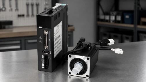
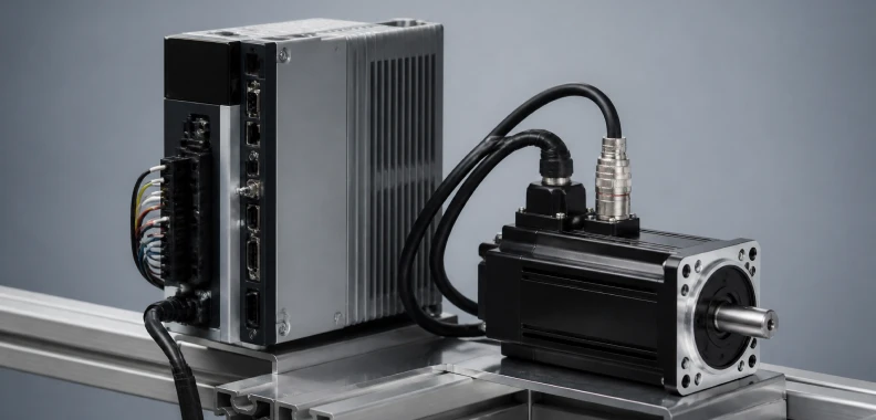
Industrial motion axes face continuous external disturbances: friction variations on linear guide rails, fluctuating payload masses, and gravitational resistance. Open-loop systems force current into a motor and assume the mechanical structure executes the command. When an axis requires guaranteed positional accuracy regardless of dynamic load changes, engineers deploy an AC servo system. The servo drive is the computational engine of this closed-loop architecture. It interprets low-level command signals from a machine controller, supplies high-voltage power to the motor, continuously reads the actual rotor position from an encoder, and mathematically corrects the error between the commanded and actual position in real time.
A drive is not a passive power supply. It is an active, high-frequency amplifier executing complex mathematical algorithms thousands of times per second. Selecting the correct servo motors and drives requires understanding their internal PID (Proportional-Integral-Derivative) structure, bandwidth limits, regeneration handling, and communication protocols. This guide documents the operational mechanics of AC servo drives and establishes the engineering criteria for specifying them in automation machinery.
1. The Cascaded PID Architecture: Three Nested Loops
The primary function of a servo drive is error correction. Modern digital servo drives achieve this through a cascaded structure of three distinct, nested control loops. Each loop monitors a specific physical parameter and feeds its output to the loop inside it.
- The Position Loop (Outer Loop): This is the slowest loop, typically updating at 1 kHz to 4 kHz. It receives the target coordinate from the CNC or PLC. It compares this target to the actual coordinate reported by the motor's encoder. The difference between the two is the "Position Error." The loop calculates the required velocity to close this distance and feeds this target speed to the velocity loop.
- The Velocity Loop (Middle Loop): Operating between 4 kHz and 8 kHz, this loop receives the speed command from the position loop. It compares the target speed against the actual derivative of the encoder data (how fast the position is changing). If the motor is moving too slowly due to mechanical friction, the velocity loop increases its output signal, which is a torque (current) command, passing it to the inner loop.
- The Current/Torque Loop (Inner Loop): This is the fastest loop in the drive, updating at 16 kHz to 32 kHz. It receives the target torque from the velocity loop. Using Field-Oriented Control (FOC), it calculates the exact electrical current vector required to generate that torque. The drive then modifies the PWM (Pulse Width Modulation) signal to push that exact current into the motor's stator windings.
Tuning a servo drive involves adjusting the Proportional (P), Integral (I), and Derivative (D) gains for these loops to match the specific mass and inertia of the mechanical load.
2. Power Amplification and PWM Switching
To supply physical power to the motor, the drive rectifies incoming AC mains power (e.g., 220VAC single-phase or 380VAC three-phase) into a high-voltage DC bus. This DC voltage is stored in large internal capacitors.
The drive utilizes an Inverter bridge composed of six IGBTs (Insulated-Gate Bipolar Transistors). The current loop controls these transistors, switching them on and off at a very high carrier frequency (typically 8 kHz to 16 kHz). This rapid switching process, known as Pulse Width Modulation (PWM), slices the DC bus voltage to synthesize a three-phase AC sine wave. By varying the width of the pulses, the drive precisely regulates both the frequency (which controls motor speed) and the amplitude (which controls motor torque) of the current flowing into the motor.
3. The Role of High-Resolution Feedback
A servo drive is entirely blind without a feedback device. The performance of the three nested loops is strictly bound by the quality of the data they receive from the motor's encoder. Industrial AC servo systems utilize absolute or incremental encoders mounted to the rear shaft of the motor.
Modern systems heavily favor absolute encoders with 17-bit, 20-bit, or 23-bit resolution. A 23-bit encoder divides a single mechanical revolution into 8,388,608 distinct units. While standard CNC ball screws do not require sub-micron physical accuracy, this extreme electronic resolution is mathematically required for the velocity loop. Because velocity is calculated by taking the derivative of position over time (dx/dt), low-resolution encoders provide coarse, "stair-step" data at low speeds. A 23-bit encoder provides continuous, smooth positional data, allowing the velocity loop to calculate precise speed derivatives even when the motor is rotating at 1 RPM. This eliminates low-speed jitter and provides immense mechanical stiffness at a standstill.
4. Speed Response Bandwidth: The Primary Performance Metric
When comparing specifications between tier-one and tier-two servo drives, engineers evaluate the Speed Response Bandwidth, measured in Hertz (Hz). Bandwidth defines how fast the drive can react to a sudden change in the speed command or an unexpected load disturbance.
A drive with a 1.0 kHz (1,000 Hz) bandwidth can adjust its torque output to a disturbance within 1 millisecond. Advanced units, such as our RS3 servo drive series, boast bandwidths exceeding 3.2 kHz (3,200 Hz). Higher bandwidth directly reduces the "settling time"—the microscopic window of time the machine must wait for the motor to stop vibrating and lock into its final coordinate after a rapid move. In high-speed pick-and-place robots or electronic component insertion machines, cutting the settling time from 5 milliseconds to 1 millisecond shaves hours off the total annual production cycle.
5. Selection Criteria 1: Matching Drive Capacity to the Motor
Unlike open-loop systems where voltage and inductance dictate performance, servo drives are selected based primarily on continuous and peak current capacity.
Continuous Current: The drive's continuous RMS rating must equal or exceed the rated continuous current of the connected servo motor. This ensures the drive can supply the thermal requirement for moving the continuous payload.
Peak Current (Overload Capacity): AC servo motors are designed to operate at 300% of their continuous torque rating for short durations (typically 3 to 5 seconds) during extreme acceleration or emergency deceleration. The selected drive must possess internal IGBTs capable of supplying this 300% peak current. If a 1.0 kW motor requires 5A continuous and 15A peak, sizing the drive purely on the 5A continuous rating will cripple the machine's dynamic acceleration envelope.
6. Selection Criteria 2: Managing Regenerative Energy
A fundamental law of physics dictates that moving mass possesses kinetic energy. When a servo drive decelerates a heavy gantry or lowers a vertical axis, the motor acts as a generator. It converts the mechanical kinetic energy back into electrical energy and forces it back into the drive. This is known as regeneration.
The drive stores this returning energy in its DC bus capacitors. If the kinetic energy exceeds the capacitance limit, the DC bus voltage will spike, triggering an Over-Voltage fault (OVP) and shutting down the axis. To manage this, drives utilize regenerative braking circuits.
- Internal Capacitance: Sufficient for light, horizontal axes with low inertia and mild deceleration ramps.
- Internal Bleeder Resistor: Most industrial drives between 400W and 2.0kW include an internal resistor. When the bus voltage reaches a critical threshold, a transistor dumps the excess energy into this resistor, burning it off as heat.
- External Braking Resistor: For high-mass applications, rapid reversing mechanisms, or heavy Z-axis (vertical) loads driven by gravity, the internal resistor cannot dissipate heat fast enough. Engineers must calculate the total regenerative energy (in Joules) and specify a heavy-duty external resistor wired directly to the drive's specific P/B or B1/B2 terminals.
7. Selection Criteria 3: Communication Protocols
The method the drive uses to receive commands from the primary controller dictates the machine's interpolation capabilities. Drives generally accept three categories of command architecture:
Pulse and Direction (Step/Dir): The legacy standard. The controller sends 5V or 24V square waves. This method is cheap, universally understood, and suitable for single-axis indexing or simple CNC routers. It is limited by signal noise susceptibility and the physical bandwidth of the optocouplers, making it insufficient for rigid multi-axis synchronization.
Analog Control (+/- 10V): The drive receives an analog voltage representing target velocity or torque, while the position loop is closed inside the main CNC controller. This remains common in legacy machine tool retrofits but suffers from analog signal drift and ground loop interference.
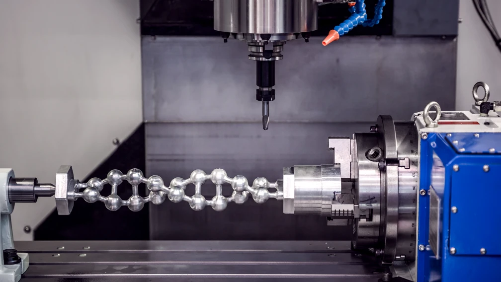
Deterministic Industrial Ethernet: Protocols like EtherCAT, PROFINET, and MECHATROLINK represent the modern standard. Digital packets transmit absolute position commands, read real-time torque limits, and capture error codes over a single standard Ethernet cable. EtherCAT, for example, synchronizes dozens of axes with microsecond precision, enabling complex 5-axis CNC contouring and robotic path interpolation without electrical noise concerns.
8. Core Selection Workflow for System Integrators
Question: How do engineers verify a servo drive specification before procurement?
Answer: Engineers first define the mechanical continuous and peak torque required by the payload, selecting a motor that meets these metrics. Second, they match the drive's continuous and 300% peak current ratings to the motor. Third, they calculate the kinetic energy of the load during the most aggressive deceleration ramp to determine if an external regenerative resistor is necessary. Finally, they specify the communication hardware (e.g., EtherCAT vs. Pulse/Direction) based on the master CNC or PLC architecture.
Engineering Support and Drive Configuration
Deploying a closed-loop motion architecture requires precise calculation of inertia ratios, regeneration limits, and loop bandwidths. Cymotorix engineers industrial automation hardware ranging from integrated motor drivers for compact applications to high-power standalone units like the RA3 servo drive platform. Our technical department supplies complete 3D models, EtherCAT XML configuration files, and software auto-tuning utilities to streamline machine commissioning. Contact our application engineering team for a formal review of your payload calculations and drive architecture.
Frequently Asked Questions (FAQ)
Question: What is the mechanical difference between a servo drive and a Variable Frequency Drive (VFD)?
Answer: A VFD is designed to run standard AC induction motors at variable speeds using open-loop frequency control, primarily for pumps, fans, and conveyors. A servo drive is a precision closed-loop amplifier that uses encoder feedback to control exact shaft position, velocity, and torque down to fractions of a degree. Servo drives handle dynamic, high-acceleration positioning, whereas VFDs manage steady-state continuous rotation.
Question: How does a servo drive's auto-tuning function work?
Answer: Modern drives feature software auto-tuning algorithms that command the motor to execute short, sudden movements back and forth. The drive measures how the motor responds to these commands compared to the expected outcome. It uses this empirical data to calculate the mechanical load's inertia and automatically populates the Proportional, Integral, and Derivative (PID) gain parameters to optimize axis stability.
Question: Why does my servo drive immediately trigger an over-voltage fault when it tries to stop?
Answer: You are experiencing excessive regenerative energy. When a heavy mass decelerates quickly, the motor acts as a generator and pumps voltage back into the drive. If the internal capacitors and standard braking resistor cannot absorb this energy fast enough, the drive shuts down to protect its circuitry. You must wire an external regenerative braking resistor to the drive to dissipate the excess energy as heat.
Question: What is electronic gearing in a servo drive setup?
Answer: Electronic gearing is a drive parameter that scales the incoming pulse commands from the controller. If an encoder requires 8,388,608 pulses for one revolution, standard PLCs cannot generate pulses fast enough to spin the motor at high speeds. The electronic gear ratio multiplies the incoming pulses (e.g., 1 incoming pulse equals 1,000 motor steps) so the controller can drive the motor at maximum RPM using low-frequency signals.
Question: Can I mix different brands of servo motors and servo drives?
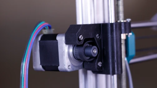
Answer: Generally, no. Unlike standard stepper motors, AC servo motors rely on proprietary absolute encoders and precise commutations derived from specific internal magnetic alignments. The proprietary serial communication protocol between a motor's encoder and its matched drive means they must be purchased and operated as a designated pair from the same manufacturer.
Question: What does a "following error" or "position tracking error" fault indicate?
Answer: This fault indicates that the actual physical position of the motor has fallen too far behind the target position commanded by the drive's trajectory planner. This is typically caused by severe mechanical binding, an undersized motor unable to overcome the required acceleration torque, or a PID loop that is tuned too loosely (low proportional gain) to enforce rigid tracking.
-

Cymotorix
Stepper Motor & Servo Motor Manufacture
Cymotorix is a China-based motor manufacturer with 20+ years of experience producing hybrid stepper motors, AC servo motors, and matched drivers for OEM customers worldwide.