
The Fallacy of the Holding Torque Specification
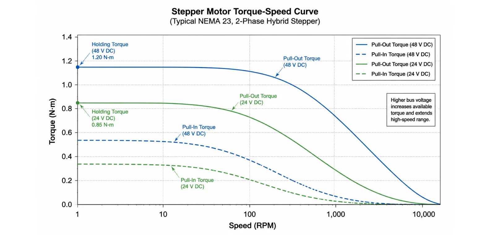
When selecting actuation hardware for industrial automation, relying solely on the catalog holding torque specification is a primary cause of mechanical axis failure. Holding torque merely defines the motor's static capacity at zero RPM. In any functional motion application, the motor must rotate, accelerate mass, and overcome dynamic friction. As a stepper motor accelerates, its available output torque decays exponentially due to inductive reactance and back-electromotive force (Back-EMF).
To guarantee an axis will not stall, lose steps, or resonate, engineers must evaluate the motor's performance across its entire operating velocity range. This evaluation requires interpreting the dynamic torque-speed curve provided by the manufacturer. This technical manual defines the four distinct torque domains of stepper motors—detent, holding, pull-in, and pull-out—and explains the physical limits that govern high-speed torque decay.
1. The Static Metrics: Detent Torque and Holding Torque
Static torque parameters define how the motor behaves when it is commanded to maintain a fixed coordinate.
Detent Torque (Unpowered): Detent torque is the residual magnetic holding force present when the motor is completely powered off. It is caused by the permanent magnet inside the hybrid rotor seeking alignment with the steel teeth of the unpowered stator. It typically represents 5% to 20% of the motor's rated holding torque. Engineers rely on detent torque in vertical Z-axis applications (like 3D printer beds or fluid dispensing heads) to prevent the axis from crashing down under gravity when machine power is cut.
Holding Torque (Powered): Holding torque is the maximum external force that can be applied to the motor shaft at zero RPM before the rotor breaks away from the stator's magnetic field and slips. This metric is measured when the motor is supplied with its full rated continuous DC current. While holding torque provides a baseline for comparing motor frame sizes, it is strictly a static measurement and cannot be used to calculate dynamic acceleration capabilities.
2. The Pull-In Torque Boundary (The Start/Stop Region)
The pull-in torque curve represents the most demanding dynamic state of an open-loop stepper motor. It defines the maximum torque boundary at which a motor can start, stop, or reverse direction instantaneously, without the aid of an acceleration or deceleration ramp.
If the load parameters (friction plus inertia) fall underneath the pull-in curve for a given pulse frequency, the motor will lock into synchronism immediately upon receiving the first pulse. If the required torque exceeds the pull-in boundary, the rotor cannot accelerate fast enough to catch the rotating stator field within a single step pulse. The motor will instantly desynchronize, emit a high-pitched stall buzz, and fail to rotate. Because instantaneous starting demands massive acceleration torque to overcome load inertia (T = J × α), the pull-in curve is always lower than the pull-out curve and drops off sharply at relatively low speeds (typically below 300 RPM).
3. The Pull-Out Torque Boundary (The Slew Region)
The pull-out torque curve defines the absolute maximum dynamic torque the motor can output at any given speed without stalling. Operating a motor between the pull-in curve and the pull-out curve requires entering the "slew region."
To reach an operating point within the slew region, the motor cannot be started instantaneously. The controller must feed the motor drivers a trapezoidal or S-curve acceleration profile, starting at a frequency below the pull-in limit and gradually ramping up the step rate. As long as the load torque combined with the acceleration torque remains safely below the pull-out curve, the motor will remain synchronized. If the load torque spikes (e.g., a cutting tool hitting a hard material knot) and crosses above the pull-out line, the motor will break its magnetic lock and stall. Engineers standardly apply a 1.5x to 2.0x safety factor beneath the pull-out curve when sizing an axis to absorb transient load spikes and mechanical wear over time.
4. The Physics of High-Speed Torque Decay
The defining characteristic of any stepper motor torque-speed curve is its dramatic downward slope at high velocities. This decay is governed by two electrical phenomena: winding inductance and Back-EMF.
- Inductive Reactance (L): Motor stator coils act as inductors. Inductors resist rapid changes in electrical current (di/dt). When the motor is rotating slowly, the driver has ample time during each step pulse to push the current up to the motor's rated limit. At high speeds (e.g., 1,000 RPM), the step pulses occur at a high frequency. The inductance prevents the current from reaching the peak value before the next step commutation occurs. Since torque is directly proportional to current, the inability to reach peak current causes torque to plummet.
- Back-Electromotive Force (Back-EMF): As the magnetized rotor spins past the stator coils, it acts as a generator, producing a voltage that opposes the driver's supply voltage. At high rotational velocities, this Back-EMF becomes substantial, further restricting the driver's ability to force current into the windings.
5. Engineering Methods to Manipulate the Torque Curve
When a machine design requires higher torque at elevated RPMs, engineers manipulate the electrical parameters rather than simply specifying a larger motor frame. A larger frame size increases holding torque but also increases winding inductance, which can actually worsen high-speed performance.
Increasing Bus Voltage: The most direct method to combat inductive reactance is raising the driver's DC supply voltage. A higher voltage forces the current through the inductor faster. Doubling the supply voltage from 24VDC to 48VDC will drastically flatten the pull-out curve, extending the usable torque range much deeper into the high-speed operating envelope. The theoretical maximum voltage is calculated as V = 32 × √(Inductance in mH).
Parallel Winding Configuration: When specifying an 8-lead motor, engineers can wire the half-windings in parallel rather than in series. Parallel wiring drops the phase inductance to 25% of the series value. This heavily reduces inductive reactance, preserving the pull-out torque at high RPMs, though it requires the driver to supply double the phase current.
6. System Diagnostics and Sizing Validation
Question: How do automation engineers validate that an open-loop stepper motor will not stall during high-speed machine indexing?
Answer: Engineers plot a scatter point on the manufacturer's torque-speed graph representing the worst-case operating condition. This point is determined by the maximum target RPM (X-axis) and the sum of steady-state friction torque plus dynamic acceleration torque (Y-axis). If this coordinate falls inside the slew region and maintains a 50% clearance below the manufacturer's pull-out torque curve, the axis is mathematically validated. If the coordinate approaches or crosses the pull-out boundary, the engineer must increase the bus voltage, lengthen the acceleration time to reduce dynamic torque demand, or upgrade the axis to a closed-loop platform.
7. The Closed-Loop Torque Advantage
When operating near the limits of the pull-out curve, open-loop systems risk catastrophic desynchronization. Upgrading to a closed-loop stepper motor alters the operational limit. By utilizing high-resolution encoder feedback and Field-Oriented Control (FOC), the closed-loop drive continuously modulates the current vector to match the exact load requirement. If the mechanical load momentarily exceeds the pull-out capability, a closed-loop system will not lose steps or stall; instead, it will dynamically increase phase current to its absolute peak limit and temporarily lag the command profile, subsequently catching up once the transient load clears.
Engineering Support and Drive Integration
Correctly interpreting torque-speed curves ensures mechanical reliability and prevents the over-sizing of automation components. Cymotorix provides comprehensive dynamic pull-out torque charts for our entire lineup of hybrid and closed-loop motion solutions. Our engineering team assists OEMs in executing kinematic calculations to verify that acceleration profiles remain safely within the continuous operating envelope. Access detailed datasheets and motor curves via our download center, or contact our technical applications team to specify the optimal motor and driver combination for your specific load parameters.
Frequently Asked Questions (FAQ)
Question: Why does my stepper motor have plenty of torque when stopped, but stalls easily when moving fast?
Answer: You are experiencing the limits of the pull-out torque curve. At zero RPM, the motor generates its maximum holding torque. As speed increases, winding inductance prevents the electrical current from reaching its maximum value during the short step pulses. Because torque is proportional to current, the available mechanical torque drops significantly at high speeds.
Question: What is the difference between pull-in torque and pull-out torque?
Answer: Pull-in torque is the maximum torque a motor can output when starting instantly from zero RPM to a specific speed without using an acceleration ramp. Pull-out torque is the absolute maximum torque the motor can generate at a specific speed after it has been safely accelerated up to that speed using a software motion profile.
Question: How much safety margin should I leave below the pull-out torque curve?
Answer: Industrial standard practice requires maintaining a safety margin of 50% to 100% (a safety factor of 1.5 to 2.0) beneath the published pull-out torque curve. This margin absorbs unpredictable variables such as fluctuating guide rail friction, bearing wear over time, ambient temperature changes, and minor voltage drops in the power supply.
Question: Can microstepping increase my motor's pull-out torque at high speeds?
Answer: No. Microstepping significantly reduces low-speed mechanical resonance and acoustic noise, but it does not increase the raw output torque envelope. In fact, operating at very high microstep resolutions (e.g., 1/128) at high speeds can sometimes reduce effective torque if the controller cannot output pulse frequencies fast enough to maintain smooth commutation.
Question: How can I flatten the torque curve to get more high-speed torque without changing the motor?
Answer: The most effective method is to increase the DC supply voltage to the stepper motor driver, provided the driver can handle the higher voltage. Doubling the supply voltage (e.g., from 24V to 48V) forces current through the motor's inductance much faster, significantly preserving torque at higher RPMs.
Question: What is detent torque and why is it useful?
Answer: Detent torque is the natural magnetic holding force of the motor when it is completely disconnected from electrical power. It is highly useful in Z-axis applications, such as heavy tool heads or vertical platforms, because it acts as a passive mechanical brake that prevents the axis from falling due to gravity during a power failure.
-

Cymotorix
Stepper Motor & Servo Motor Manufacture
Cymotorix is a China-based motor manufacturer with 20+ years of experience producing hybrid stepper motors, AC servo motors, and matched drivers for OEM customers worldwide.