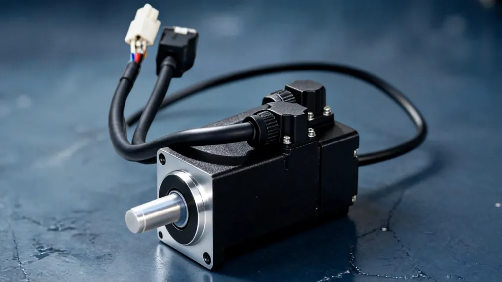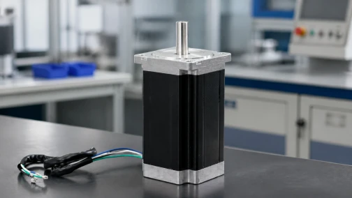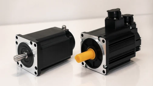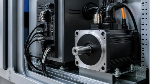

The Engineering Reality of Closed-Loop Stepper Stability
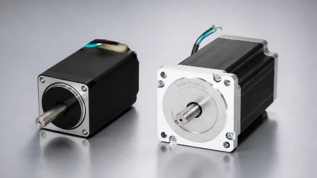
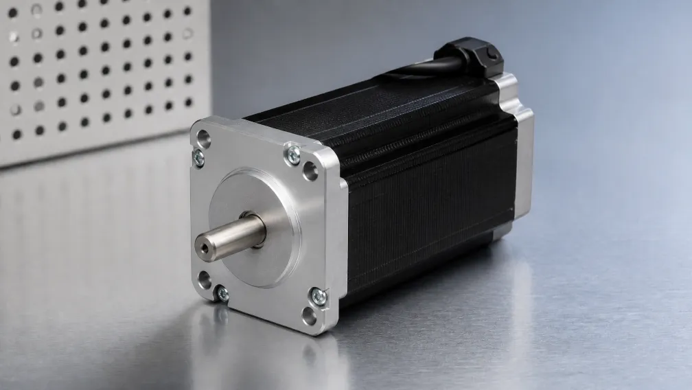
Integrating an encoder onto a standard stepper motor creates a closed-loop actuation platform that eliminates open-loop step loss. However, adding feedback introduces a new control dynamic: loop stability. Unlike a traditional open-loop system that operates without regard for external positional deviations, a closed-loop stepper drive continuously monitors the rotor position and adjusts the phase current vector to correct detected errors. When these correction parameters are misconfigured, the motor can begin to oscillate, vibrate, or exhibit positional "hunting" at rest.
Achieving optimal performance requires tuning the internal Proportional-Integral (PI) control loops of the drive. This technical guide examines the root causes of over-correction, defines the mechanics of positional hunting, and outlines step-by-step procedures for tuning closed-loop closed loop stepper motors to achieve rigid stability without sacrificing dynamic response.
1. The Control Loop Architecture: FOC and Current Vector Shifting
A modern closed-loop stepper drive executes Field-Oriented Control (FOC) synchronized with an optical or magnetic encoder (typically ranging from 1,000 to 4,000 pulses per revolution). The drive tracks the command trajectory and compares it against the real-time physical position of the rotor.
If an external mechanical resistance causes the rotor to lag behind the command pulse stream, the drive's internal algorithm calculates a position error and shifts the current vector magnitude and phase angle to generate an aggressive restoring force. While this mechanism prevents permanent stalling, an overly aggressive gain setting causes the drive to over-correct. The rotor snaps past the target coordinate, triggers an error in the opposite direction, and establishes a continuous mechanical oscillation known as hunting.
2. Identifying Symptoms: Hunting, Dithering, and Audible Buzz
Diagnosing unstable loop tuning relies on identifying specific physical behaviors during standstill or low-speed operation:
- Standstill Dithering: The motor shaft oscillates back and forth within a microscopic window of a few encoder counts while at rest. This is accompanied by a high-frequency audible buzz.
- Overshoot Oscillation: When the axis completes a point-to-point movement, the motor overshoots the target coordinate and rocks back and forth two or three times before settling. This extends the total settling time and slows down machine cycle rates.
- Mid-Travel Instability: The motor runs smoothly at high speeds but vibrates or chatters harshly during low-speed indexing or fine contouring movements.
These symptoms indicate that the Proportional (P) gain is set too high, or the Integral (I) time constant is too short, causing the drive to react too violently to minor feedback discrepancies.
3. Tuning Proportional (P) Gain: Stiffness vs. Oscillation
The Proportional gain parameter dictates how aggressively the drive reacts to a position error. Increasing the P gain increases the system's static and dynamic stiffness, forcing the motor to resist external mechanical loads more rigidly.
However, setting the P gain beyond the physical limits of the mechanical transmission creates an under-damped system. The motor treats the high gain as an invitation to snap instantly to the target, ignoring the mechanical compliance of the belt, coupling, or ball screw. To tune P gain safely, start at a low baseline value where the motor feels "soft" and exhibits slight tracking lag. Gradually increase the gain until the axis tracks the command trajectory crisply without any audible ringing or overshoot when coming to a stop.
4. Tuning Integral (I) Gain: Eliminating Steady-State Error
While Proportional gain handles immediate error magnitude, the Integral gain accumulates position error over time. Its primary function is to eliminate steady-state error—ensuring that the motor reaches the exact absolute coordinate demanded by the controller rather than stopping one or two microsteps short due to mechanical friction.
If the Integral gain is set too high (or the integration time constant is set too short), the drive continuously accumulates historical error values, leading to wind-up. This causes the motor to build excessive corrective force, overshoot the target violently, and enter a continuous oscillation cycle. Effective tuning requires balancing P and I gains so that static holding is rock-solid without introducing low-frequency drift or hunting.
5. Encoder Resolution and Filter Settings
The stability of a closed-loop control loop is heavily dependent on the signal quality of the feedback device. High-resolution encoders (such as 4,000 PPR units) provide granular positional data, but they also capture high-frequency mechanical vibration and electrical noise from nearby motor drivers.
If raw encoder noise enters the drive's error calculation algorithm, the drive treats the electrical jitter as real physical movement and attempts to correct it, causing unnecessary current fluctuations and audible dither. To prevent this, modern drives incorporate configurable digital low-pass filters on the encoder input channel. Adjusting the filter bandwidth allows the drive to smooth out high-frequency electrical jitter while maintaining rapid response to genuine mechanical motion.
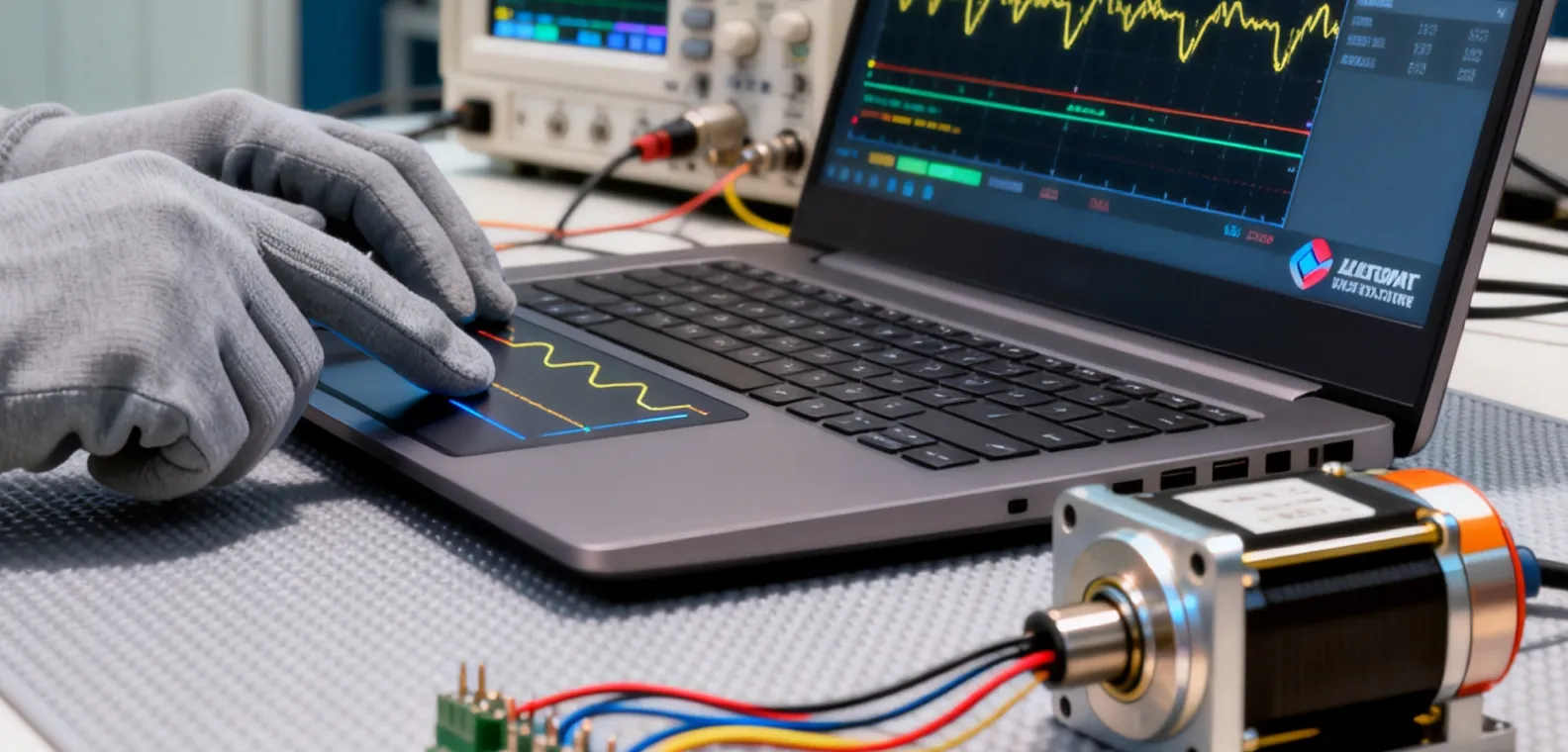
6. Engineering Selection Criteria for Closed-Loop Retrofits
Question: How do automation engineers determine whether an oscillating axis requires drive parameter tuning or a fundamental hardware adjustment?
Answer: Engineers perform a systematic check: First, they reduce the Proportional gain in the drive software; if the hunting and high-frequency buzz disappear instantly, the issue was software over-correction. Second, if reducing software gains creates unacceptable tracking lag or position errors under load, the root cause is mechanical compliance—such as a loose shaft coupling, stretched timing belt, or an excessive inertia mismatch ratio exceeding 30:1—which requires mechanical stiffening or upgrading to a heavy-duty servo motors platform.
7. Comparing Closed-Loop Steppers with Standard Open-Loop and Servo Systems
Understanding where closed-loop steppers sit in the motion control spectrum helps clarify their tuning behavior:
| Motion Architecture | Feedback Loop | Tuning Requirement | Typical Application Limit |
| Open-Loop Stepper | None (Open loop) | None required (Current set only) | Risk of unmonitored step loss under load |
| Closed-Loop Stepper | Encoder feedback with FOC | Basic PI loop gain adjustment | High low-speed torque with stall prevention |
| AC Servo System | Nested 3-loop PID | Complex multi-parameter tuning | High-speed multi-axis interpolation |
While an AC servo requires balancing three nested control loops (position, velocity, and current), a closed-loop stepper primarily focuses on current vector correction and basic PI loop stability, making it significantly faster to commission while delivering zero-loss reliability.
Engineering Support and Technical Resources
Properly tuning a closed-loop motion axis eliminates resonance, stops standstill hunting, and guarantees reliable, error-free production. Cymotorix manufactures high-reliability hybrid and closed-loop stepper motors equipped with advanced digital drives featuring auto-tuning utilities and low-pass filtering. Our engineering team supplies complete technical documentation, wiring diagrams, and CAD models in our download center. Contact our technical support department for assistance with parameter tuning or custom motion control architecture.
Frequently Asked Questions (FAQ)
Question: What causes a closed-loop stepper motor to make a buzzing sound and dither when standing completely still?
Answer: Standstill hunting or dithering is typically caused by Proportional (P) gain set too high, or encoder signal jitter being interpreted by the drive as actual physical movement. Lowering the P gain slightly or increasing the digital encoder filter bandwidth will eliminate the noise and lock the shaft motionless.
Question: How does a closed-loop stepper differ from an AC servo in terms of tuning complexity?
Answer: An AC servo utilizes three fully nested PID loops (position, velocity, and current) that require extensive calibration of multiple gains. A closed-loop stepper retains the high pole-count stiffness of a stepper motor and uses simpler current vector adjustment algorithms, making tuning significantly faster and more forgiving.
Question: Why does my closed-loop stepper overshoot its target coordinate before stopping?
Answer: Overshoot occurs when the drive's proportional gain is too high relative to the mechanical damping of the load. The drive reacts too aggressively to close the final positioning error, snapping past the coordinate before the control loop can decelerate the rotor.
Question: Can encoder cable noise cause positioning errors in a closed-loop stepper system?
Answer: Yes. Unshielded or poorly grounded encoder cables running parallel to high-voltage motor power lines can pick up electromagnetic interference (EMI). This noise corrupts the feedback pulses, causing the drive to mistakenly correct for phantom errors and inducing erratic vibration.
Question: Does a closed-loop stepper motor require tuning when changing the connected physical payload?
Answer: Unlike sensitive AC servos that require complete re-tuning when payload inertia changes drastically, closed-loop steppers possess high magnetic detent stiffness that absorbs moderate load variations. However, if the payload mass increases beyond the 30:1 inertia ratio limit, minor PI gain adjustments may be required.
Question: What is the function of the encoder filter parameter in a closed-loop stepper drive?
Answer: The encoder filter smooths out high-frequency electrical noise and minor mechanical jitter from the feedback signal before it reaches the error calculation algorithm, preventing the drive from reacting to false micro-movements and ensuring smooth operation.
-

Cymotorix
Stepper Motor & Servo Motor Manufacture
Cymotorix is a China-based motor manufacturer with 20+ years of experience producing hybrid stepper motors, AC servo motors, and matched drivers for OEM customers worldwide.