
The Engineering Imperative of Accurate Motor Sizing
Improper motor sizing represents one of the primary failure modes in industrial motion system design. An undersized stepper motor lacks sufficient pull-out torque to overcome dynamic mechanical resistance, leading to position tracking errors, missed steps, and unpredictable axis stalls. Conversely, an oversized motor increases unnecessary component cost, adds excessive mass to moving gantries, and increases internal rotor inertia, requiring higher driver currents and producing excessive heat dissipation that accelerates bearing degradation.
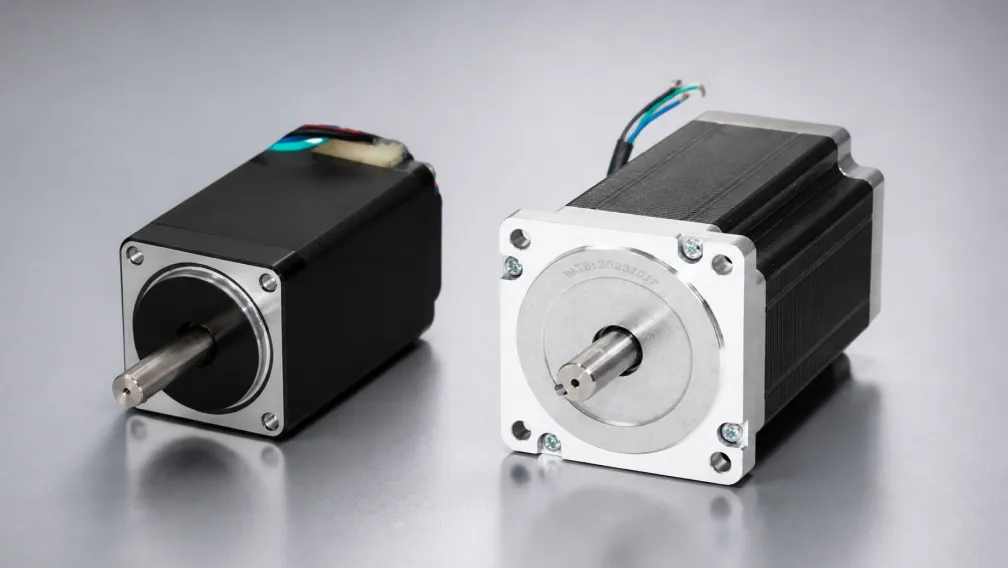
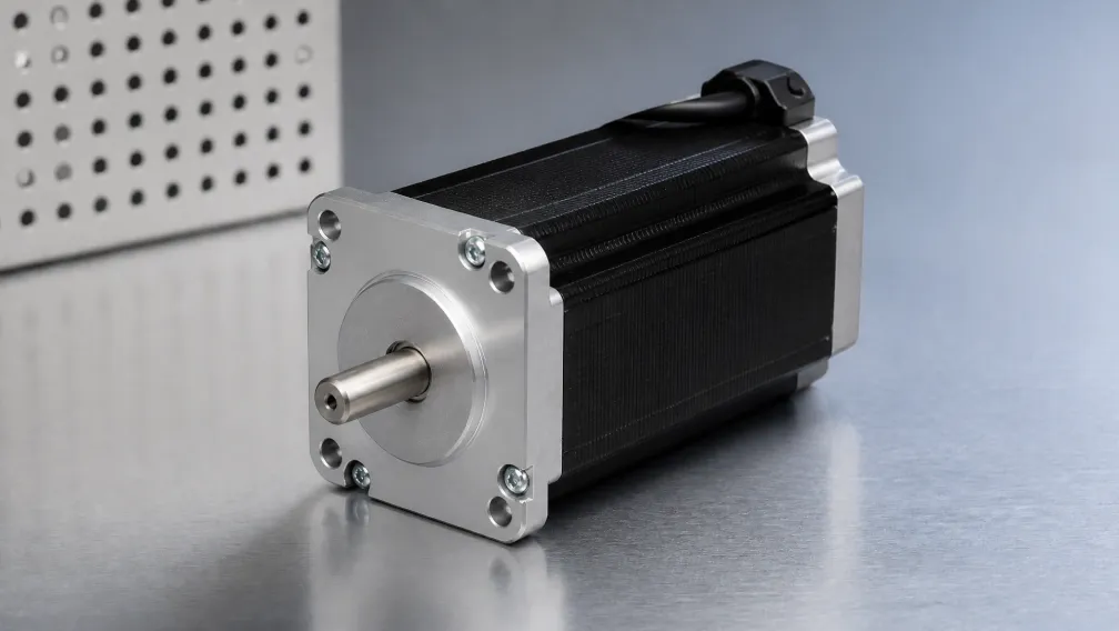
Sizing an actuation axis requires moving beyond holding torque ratings printed on catalog datasheets. Holding torque defines only the motor's static capability at zero velocity. In functional automated equipment, dynamic torque—available while the rotor accelerates against friction, gravity, and reflected load inertia—governs performance. This technical guide outlines the mathematical framework required to calculate load torque, determine total system inertia, evaluate speed-torque boundaries, and size industrial stepper motors for reliable operation.
1. Defining the Kinematic Motion Profile
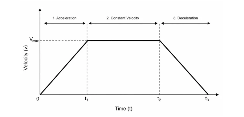
Every sizing calculation begins by establishing the required motion trajectory. Automated mechanisms typically follow a trapezoidal or S-curve velocity profile consisting of three distinct phases: acceleration (ta), constant velocity (tv), and deceleration (td).
To calculate required angular velocities and accelerations, convert linear mechanism displacements into rotational parameters at the motor shaft:
- Maximum Rotational Velocity (ω_max): For a lead screw mechanism with lead p (meters per revolution) driving an axis at linear speed v (m/s), rotational speed is calculated as: ω_max = (v / p) × 2π (rad/s) or N_max = (v × 60) / p (RPM).
- Angular Acceleration (α): Assuming a constant linear acceleration ramp over time ta: α = ω_max / ta (rad/s²).
Because dynamic torque requirements peak during the acceleration phase, narrowing the acceleration window (ta) directly inflates torque demands. S-curve acceleration profiles reduce mechanical jerk, but require approximately 15% to 20% higher peak acceleration rates than linear ramps to achieve the same overall move time.
2. Calculating Constant Load and Friction Torque (T_L)
Constant load torque (T_L) represents the continuous resistance the motor must overcome regardless of acceleration. This includes mechanical friction, preload forces, and gravitational loads on vertical axes.
Lead Screw and Ball Screw Drives
For horizontal screw-driven axes, load torque depends on total payload mass (m), coefficient of friction of linear guide rails (μ), screw lead (p), and mechanical transmission efficiency (η):
T_friction = (μ × m × g × p) / (2π × η)
If the screw operates vertically, the full gravitational force acts directly against the motor:
T_gravity = (m × g × p) / (2π × η)
Ball screws generally exhibit efficiencies (η) between 0.85 and 0.95, whereas standard lead screws with bronze or polymer nuts operate between 0.35 and 0.65. This lower efficiency significantly increases the continuous torque demand.
Timing Belt and Pulley Drives
For timing belt systems, the load torque is a function of total frictional force (F_f = μ × m × g) and the pitch radius of the drive pulley (r_p):
T_friction = (F_f × r_p) / η
Belt drive systems typically achieve transmission efficiencies (η) of 0.90 to 0.95, assuming proper belt tensioning without excessive bearing preload.
3. Reflected Inertia and Acceleration Torque (T_A)
Newton's second law for rotational systems states that acceleration torque is the product of total system inertia (J_total) and angular acceleration (α): T_A = J_total × α. Total system inertia consists of the internal motor rotor inertia (J_m) plus all external load inertias reflected back to the motor shaft (J_L).
Calculating Reflected Load Inertia (J_L)
| Transmission Type | Component Inertia Formula | Reflected Mass Formula |
|---|---|---|
| Lead / Ball Screw | J_screw = 0.5 × m_screw × r_screw² | J_mass = m_load × (p / 2π)² |
| Timing Belt / Pulley | J_pulley = 0.5 × m_pulley × r_p² | J_mass = m_load × r_p² |
| Direct Rotary Table | J_disc = 0.5 × m_disc × r_disc² | J_mass = Σ (m_i × r_i²) |
The total reflected load inertia is the sum of the transmission inertia and the mass inertia: J_L = J_component + J_mass.
The Inertia Mismatch Ratio (J_L / J_m)
Maintaining a stable inertia ratio is critical for open-loop stepper stability. Because a stepper motor operates as a resonant mass-spring system, an excessive load-to-rotor inertia ratio leads to severe resonance, velocity ripple, and loss of synchronization.
- Optimal Ratio: J_L / J_m ≤ 5:1 ensures stable acceleration and rapid settling times.
- Acceptable Range: J_L / J_m between 5:1 and 10:1 operates reliably under conservative acceleration ramps.
- Unstable Threshold: Ratios exceeding 10:1 frequently cause stalling unless mitigated by mechanical reduction gearboxes or upgraded to closed-loop stepper motors that monitor position feedback dynamically.
4. Total Dynamic Sizing Equation and Pull-Out Torque Verification
Peak torque occurs during the acceleration interval when the motor must overcome both friction and inertia simultaneously:
T_required = (T_L + T_A) × S_f = [T_L + (J_m + J_L) × α] × S_f
Where S_f is the required engineering safety factor (typically 1.5 to 2.0 for open-loop steppers to account for voltage fluctuations, temperature swings, and mechanical wear).
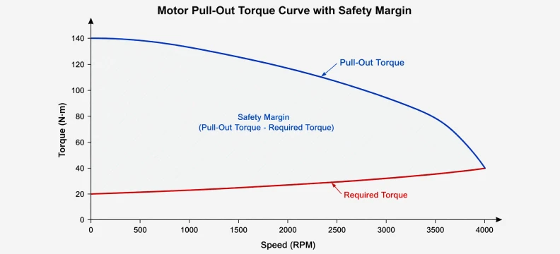
Once T_required and maximum operating speed (N_max) are calculated, verify the operating point against the manufacturer's **Pull-Out Torque Curve**. The selected motor must supply torque exceeding T_required across the entire operating speed range, not merely at zero RPM.
5. The Core Sizing Decision Workflow
Question: How do engineers quickly evaluate whether a selected motor can fulfill an axis duty cycle without risking mid-stroke stalls?
Answer: Engineers plot the system's worst-case operating point—defined by maximum angular acceleration torque combined with steady-state friction torque—onto the motor's dynamic pull-out torque curve at peak operating RPM. If the curve provides at least a 30% to 50% torque margin (S_f ≥ 1.5) above the required torque line across the entire velocity profile, and the inertia mismatch ratio (J_L / J_m) remains below 10:1, the motor is mathematically validated for stable continuous operation.
6. Electrical Supply Voltage and Inductance Matching
Mechanical calculations assume the motor receives sufficient phase current across its speed range. However, winding inductance (L) generates electrical reactance that resists current rise as switching frequencies increase with motor RPM. To maintain dynamic torque at higher speeds, the power supply voltage (V_bus) must be sized appropriately.
A practical engineering guideline for calculating optimal supply voltage based on motor inductance is:
V_optimal ≈ 32 × √L (in mH)
If a NEMA 23 stepper motor has a phase inductance of 2.5 mH, the optimal bus voltage is approximately 32 × √2.5 ≈ 50.6 VDC. Powering this motor from a 24V supply causes its pull-out torque curve to decay prematurely at roughly half its achievable velocity ceiling. Choosing matched motor drivers capable of handling higher supply voltages is essential when sizing high-speed axes.
7. Sizing Correction Strategies for High-Load Applications
When initial calculations indicate an inertia mismatch exceeding 10:1 or an excessively high required torque, engineers apply specific design adjustments:
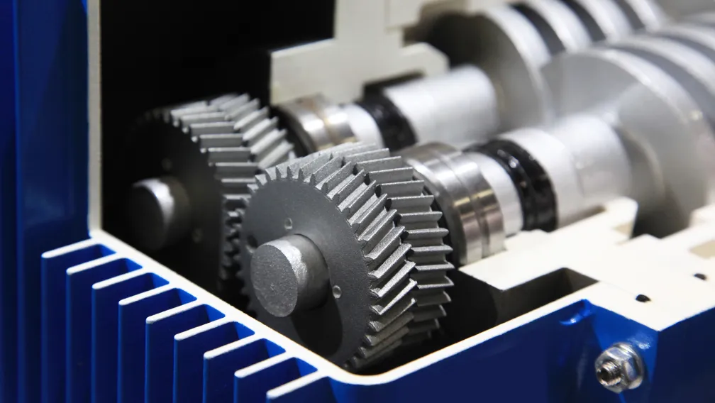
- Add a Planetary Gearbox: Installing a gearbox with gear ratio i reduces the reflected load inertia by the square of the ratio (J_reflected = J_L / i²) while multiplying output torque by i × η_gear. This resolves inertia mismatch issues in high-mass transport systems.
- Adjust Mechanical Pitch: Reducing the lead of a ball screw (e.g., from 10mm to 5mm per revolution) reduces the reflected mass inertia by 75% and halves the required driving torque, trading maximum linear speed for mechanical advantage.
- Optimize Winding Configurations: For 8-lead motors, wiring half-windings in parallel cuts phase inductance to a quarter of the series value, extending pull-out torque deeper into higher RPM ranges without altering frame size.
Engineering Consultation and Application Support
Accurate motor sizing balances mechanical transmission parameters, dynamic torque curves, inertia ratios, and drive electronics. Cymotorix manufactures high-precision hybrid and closed-loop stepper motors engineered for demanding OEM applications. Our engineering team provides direct sizing validation, dynamic load simulations, 3D CAD models, and technical datasheets through our download center. Contact our application engineers to evaluate your mechanical specifications and select the optimal motion control platform for your machinery.
Frequently Asked Questions (FAQ)
Question: What is the difference between holding torque and pull-out torque?
Answer: Holding torque is the maximum static torque a powered stepper motor can generate at zero RPM without rotating out of position. Pull-out torque is the maximum dynamic torque the motor can output at a specific rotational speed without losing synchronism or stalling. Sizing calculations must always evaluate pull-out torque at actual operating speeds rather than relying on holding torque.
Question: Why is an open-loop stepper motor sized with a 1.5 to 2.0 safety factor?
Answer: Open-loop stepper systems lack position feedback to correct tracking lag. A safety factor between 1.5 and 2.0 provides an engineering margin that absorbs friction variations, bearing wear, ambient temperature changes affecting lubricant viscosity, and minor bus voltage drops, preventing unexpected step loss.
Question: How does the load-to-rotor inertia ratio affect stepper motor positioning stability?
Answer: Because stepper motors exhibit internal magnetic stiffness acting like a torsional spring, an excessive load-to-rotor inertia ratio (exceeding 10:1) amplifies mechanical resonance. This leads to extended settling times at the end of a move, audible vibration, and an increased risk of mid-travel stalling during sudden speed changes.
Question: Can I reduce motor sizing requirements by changing the acceleration profile?
Answer: Yes. Extending the acceleration time (ta) reduces angular acceleration (α), which directly lowers the required acceleration torque (T_A = J_total × α). Additionally, implementing S-curve acceleration smoothing reduces mechanical jerk, minimizing transient current spikes and torque saturation at the start of a move.
Question: How does motor winding inductance limit achievable high-speed torque?
Answer: Inductance opposes changes in electrical current. At high rotational velocities, the driver must energize and de-energize stator coils at rapid step rates. High inductance slows down the rate of current rise (di/dt = V/L), preventing phase current from reaching its rated peak before the next step commutation occurs, which causes dynamic torque to decay.
Question: When should I select a closed-loop stepper motor over an open-loop configuration during sizing?
Answer: Closed-loop stepper motors should be selected when payload mass varies unpredictably, when inertia mismatch ratios fall in the 10:1 to 30:1 range, or when the application cannot tolerate undetected step loss. The integrated encoder allows the drive to modulate current dynamically and eliminate stall failures under peak transient loads.
-

Cymotorix
Stepper Motor & Servo Motor Manufacture
Cymotorix is a China-based motor manufacturer with 20+ years of experience producing hybrid stepper motors, AC servo motors, and matched drivers for OEM customers worldwide.