
The Mechanical and Electrical Divide in Stepper Architecture
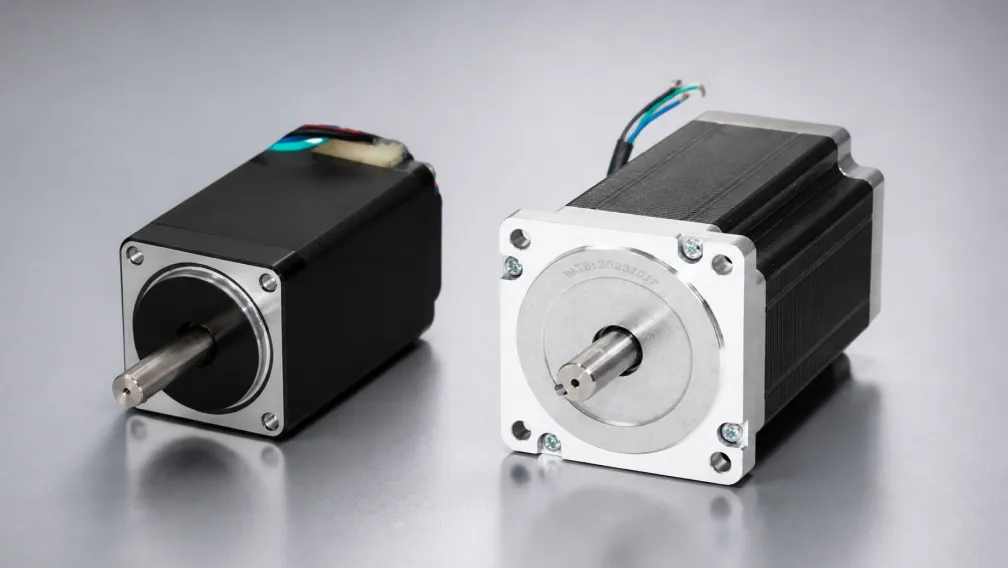
When specifying an open-loop or closed-loop stepper system, engineers frequently focus entirely on the NEMA frame size and the holding torque specification. This approach overlooks the fundamental internal geometry of the motor—specifically, the phase count. The distinction between a standard 2-phase stepper motor and a 3-phase stepper motor dictates the physical step angle, the acoustic resonance profile, and the dynamic torque retention at high speeds. While 2-phase motors dominate standard automation due to their low cost and broad driver compatibility, 3-phase architectures provide a hardware-level solution to the inherent vibration and torque ripple problems that plague high-precision indexing axes.
Understanding when to deploy a 3-phase platform requires analyzing the magnetic flux paths, stator pole configurations, and drive topologies that separate these two technologies. This technical manual details the electromechanical differences between 2-phase and 3-phase stepper architectures, outlines their respective torque-speed behaviors, and establishes clear engineering criteria for specifying them in industrial machinery.
1. Stator Geometry and the Physical Step Angle
The primary operational difference between these two platforms originates from their internal electromagnetic construction. A standard hybrid 2-phase stepper motor typically features 8 stator poles (electromagnets) and a rotor with 50 teeth. By alternately energizing Phase A and Phase B, the magnetic alignment shifts, forcing the rotor to move in 1.8-degree physical increments. This yields exactly 200 full steps per 360-degree revolution. The 1.8-degree step is the global standard for general-purpose positioning.
A 3-phase stepper motor utilizes a fundamentally different geometry, commonly featuring 6 or 12 stator poles and a specialized rotor. The addition of the third phase alters the magnetic alignment geometry, resulting in a native physical step angle of 1.2 degrees. This configuration requires 300 full steps to complete one revolution. This 50% increase in native mechanical resolution is entirely hardware-based and does not rely on the electrical interpolation (microstepping) generated by the driver. A finer physical step angle means the rotor travels a shorter distance between magnetic lock points, which directly reduces the kinetic energy generated during each step pulse.
2. Vibration, Resonance, and Acoustic Profiles
Vibration is the most persistent challenge in stepper motor integration. Every time a step pulse is executed, the rotor accelerates toward the next magnetic pole, overshoots slightly, and oscillates before settling. This mass-spring behavior causes low-frequency mechanical resonance, typically peaking between 100 and 200 RPM in 2-phase motors.
Because a 3-phase motor takes smaller 1.2-degree steps, the rotor overshoot and the subsequent ringing amplitude are drastically reduced. Furthermore, the 3-phase geometry creates a more uniform magnetic field distribution within the stator air gap. This suppresses the harmonic distortions that cause motor housing vibration. Consequently, 3-phase stepper motors run significantly quieter and smoother, completely bypassing the aggressive mid-band resonance zones that often cause 2-phase motors to stall. In applications such as automated optical inspection (AOI) or medical fluid dispensing, this native acoustic and vibrational stability is critical for preventing camera blur or fluid meniscus agitation.
3. Torque Ripple and High-Speed Dynamic Performance
Torque ripple refers to the microscopic fluctuations in rotational force as the rotor transitions from one magnetic pole to the next. In a 2-phase system, the torque output dips slightly at the midpoint between the A and B phase alignments. This ripple manifests as audible "growling" at low speeds and contributes to surface finish artifacts in CNC machining.
The overlapping magnetic fields of a 3-phase stator (Phases U, V, and W) eliminate deep null points between steps, producing a much flatter, continuous torque output. This characteristic mirrors the continuous commutation of a brushless AC servo motor. Beyond smoothness, 3-phase motors generally exhibit lower phase inductance than identically sized 2-phase motors. Lower inductance allows the motor drivers to push current into the windings faster. As a result, the dynamic pull-out torque curve of a 3-phase motor remains flat deeper into the high-speed operating envelope, allowing the axis to sustain heavier loads at velocities exceeding 1,000 RPM.
4. Drive Electronics: H-Bridge vs. 3-Phase Inverter
The phase count dictates the required hardware topology of the motor driver. A 2-phase driver utilizes two independent H-bridge circuits—one for Phase A and one for Phase B. The wiring is straightforward, typically requiring 4 leads (bipolar series or parallel). If a wire is crossed between phases, the motor will simply vibrate in place.
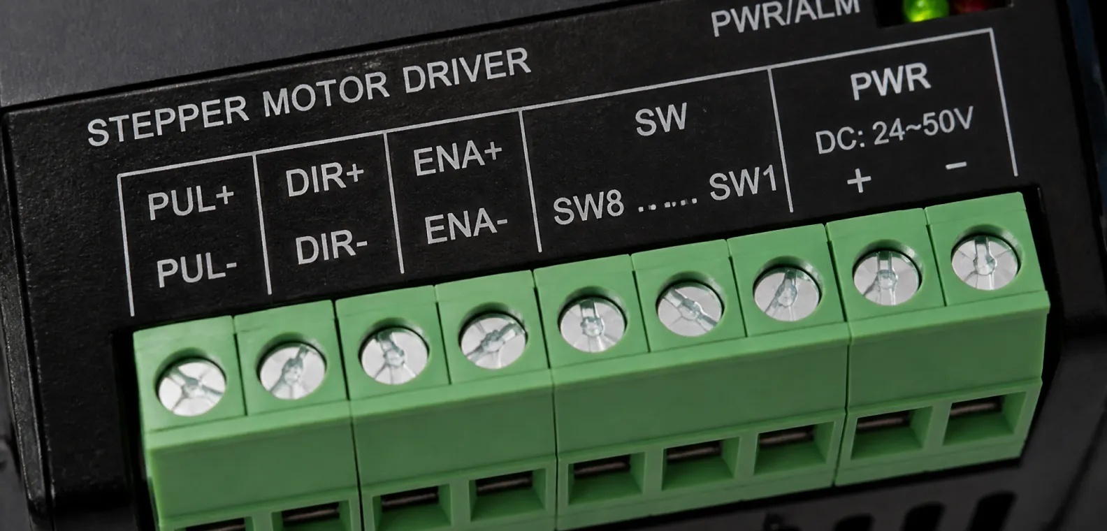
A 3-phase stepper driver operates on a completely different architecture, utilizing a 3-phase inverter bridge (six IGBTs or MOSFETs) identical to the hardware found in AC servo drives. The motor requires 3 power leads (U, V, W), often configured internally in a star (Y) or delta (Δ) winding pattern. This 3-phase commutation requires advanced vector control algorithms to maintain synchronized current delivery. Consequently, a 3-phase motor cannot be operated by a standard 2-phase bipolar chopper drive, and the dedicated 3-phase drives represent a slight cost premium over standard 2-phase electronics.
5. Integration with Closed-Loop Feedback Systems
Both 2-phase and 3-phase platforms can be upgraded to closed-loop architectures by mounting high-resolution encoders to the rear shaft. A closed loop stepper motor utilizes Field-Oriented Control (FOC) to eliminate step loss and reduce heat generation.
However, applying closed-loop control to a 3-phase motor creates a system that performs almost indistinguishably from an AC servo at low to medium speeds. The inherent low torque ripple and 1.2-degree physical resolution of the 3-phase stator allow the closed-loop PID algorithm to track the position command with minimal corrective effort. While a closed-loop 2-phase motor is robust and stall-proof, a closed-loop 3-phase motor adds the ultra-low vibration and high-speed stability required for semiconductor wafer handling and precision laser contouring.
6. Engineering Selection Criteria for Stepper Architectures
Question: How do automation engineers decide whether to specify a 2-phase or a 3-phase stepper motor for a new machine design?
Answer: Engineers evaluate the application based on acoustic limits, speed requirements, and budget constraints. If the axis is a general-purpose linear actuator, a packaging conveyor, or a desktop 3D printer where minor vibration is acceptable and cost control is paramount, the standard 2-phase motor is specified. If the axis drives a high-magnification vision system, a laser cutting head, or requires sustaining high torque at speeds above 800 RPM without the cost penalty of a full AC servo system, the engineer will specify a 3-phase stepper motor to guarantee mechanical smoothness and high-speed reliability.
7. Sizing and Upgrading Legacy Equipment
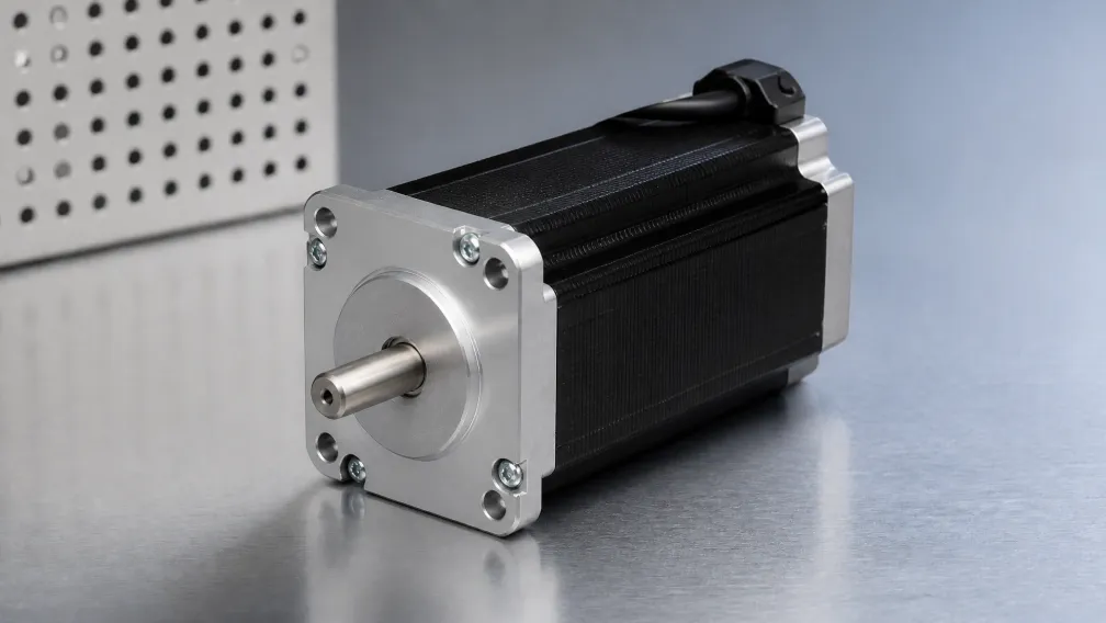
Machine builders looking to upgrade legacy equipment often face mechanical footprint restrictions. Fortunately, 3-phase stepper motors conform to the same NEMA mounting standards as 2-phase motors. A NEMA 23 or NEMA 34 3-phase motor will bolt directly into the existing bracket of an older 2-phase system. The upgrade path strictly requires replacing the drive cabinet electronics to accommodate the 3-phase inverter topology. When sizing a 3-phase motor, the same fundamental calculations for load inertia and dynamic pull-out torque apply, ensuring that the new motor meets the continuous and acceleration demands of the payload.
Engineering Support and Application Consulting
Specifying the optimal phase count requires a detailed analysis of the machine's speed profile and rigidity requirements. Cymotorix manufactures a complete portfolio of high-precision 2-phase and 3-phase stepper motors, closed-loop systems, and matched digital drives. Our engineering team assists OEMs in calculating inertia matching, evaluating pull-out torque curves, and selecting the correct stator geometry for vibration-critical applications. Complete 3D CAD files, motor dimensional drawings, and technical datasheets are available through our download center. Contact our technical applications department to review your motion requirements and customize a drive solution for your equipment.
Frequently Asked Questions (FAQ)
Question: What is the physical step angle of a 3-phase stepper motor compared to a 2-phase motor?
Answer: A standard 2-phase stepper motor has a physical step angle of 1.8 degrees, resulting in 200 full steps per revolution. A 3-phase stepper motor has a native step angle of 1.2 degrees, resulting in 300 full steps per revolution. This higher physical resolution is inherent to the stator geometry and does not rely on electronic microstepping.
Question: Can I run a 3-phase stepper motor using my existing 2-phase motor driver?
Answer: No. A 2-phase driver utilizes two distinct H-bridge circuits to control four motor wires. A 3-phase motor requires a 3-phase inverter bridge to control three power leads (U, V, W) via vector commutation. Attempting to wire a 3-phase motor to a 2-phase driver is impossible and will likely damage the drive circuitry.
Question: Why do 3-phase stepper motors produce less acoustic noise and vibration?
Answer: The 1.2-degree step angle means the rotor travels a shorter distance between magnetic detents, injecting less kinetic energy into the mechanical structure. Furthermore, the 3-phase overlapping magnetic fields eliminate the deep torque nulls between steps found in 2-phase motors, creating a continuous, smooth rotation that prevents mid-band resonance and audible whining.
Question: Do 3-phase stepper motors provide higher holding torque than identically sized 2-phase motors?
Answer: At zero RPM, the static holding torque between a 2-phase and a 3-phase motor of the same NEMA frame size and stack length is generally identical. The advantage of the 3-phase motor lies in its dynamic pull-out torque at high speeds, not its static holding power.
Question: How does a 3-phase stepper motor perform at high speeds (e.g., above 1,000 RPM)?
Answer: 3-phase stepper motors typically have lower phase inductance than 2-phase equivalents. Low inductance allows the driver to push current into the stator coils faster. This minimizes the torque-choking effects of back-EMF and inductive reactance, allowing the 3-phase motor to maintain a flatter, higher torque curve well past 1,000 RPM.
Question: Are 3-phase stepper motors available in closed-loop configurations?
Answer: Yes. Attaching a high-resolution absolute or incremental encoder to a 3-phase stepper motor creates an exceptionally smooth closed-loop system. Because the 3-phase stator naturally resists vibration, the closed-loop drive expends less processing power correcting positional jitter, resulting in performance that closely rivals high-end AC servo systems at a lower cost.
-

Cymotorix
Stepper Motor & Servo Motor Manufacture
Cymotorix is a China-based motor manufacturer with 20+ years of experience producing hybrid stepper motors, AC servo motors, and matched drivers for OEM customers worldwide.