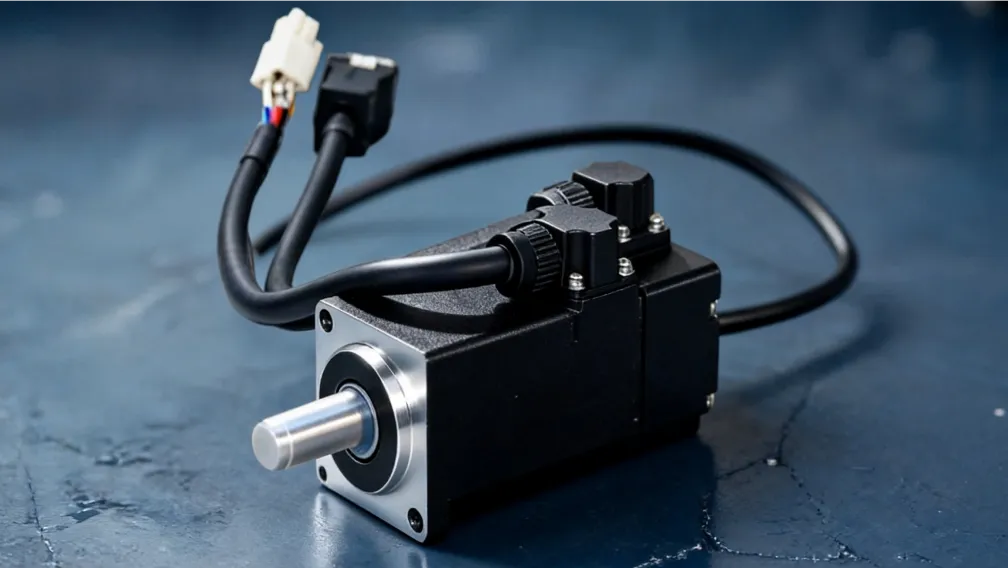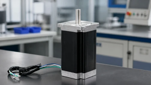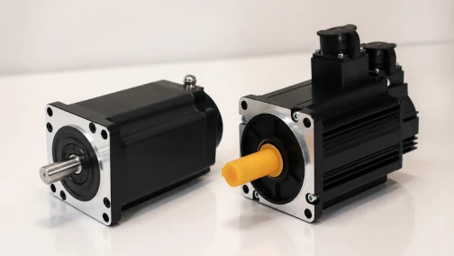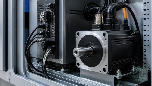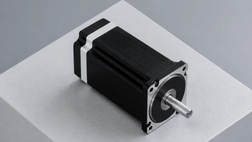

The Engineering Reality of Stepper Motor Heating
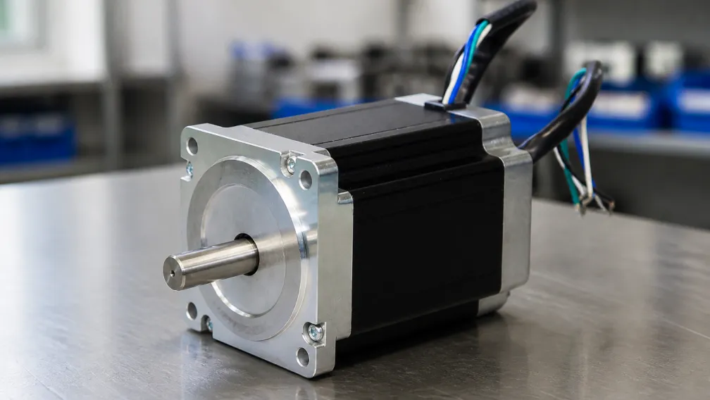
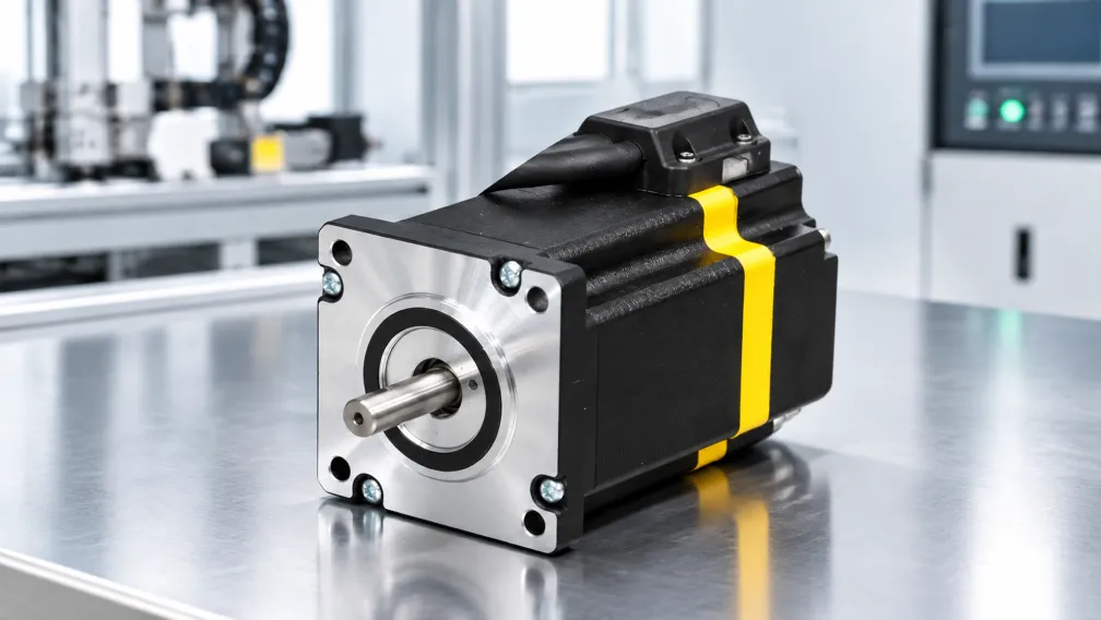
Heat generation is an inherent physical characteristic of open-loop stepper motors. Unlike standard AC induction motors or servo systems that draw current proportional to the mechanical load, a conventional stepper motor draws its full rated phase current continuously to maintain holding torque, even when the shaft is completely stationary. This fundamental operational difference means that stepper motors often run hot to the touch during normal industrial operation. Understanding the thermodynamics of these actuators is a strict requirement for machine builders designing continuous-duty automation equipment.
A surface temperature of 80°C to 90°C on a stepper motor casing is common and generally safe, provided the internal windings remain below their rated insulation limit. However, allowing a motor to exceed its thermal design envelope leads to rapid degradation of phase insulation, demagnetization of the rotor, and premature bearing failure. This technical guide examines the root causes of motor heating, details the relevant NEMA insulation classes, and provides actionable engineering strategies for thermal management at the drive, control, and mechanical levels.
1. The Physics of Heat Generation: Copper and Iron Losses
The total heat generated within a stepper motor is the sum of primarily two electromagnetic phenomena: copper losses and iron losses. The balance between these two shifts drastically depending on the operational speed of the axis.
Copper Losses (I²R Heating)
Copper loss, or Joule heating, is the dominant source of heat when the motor is stationary or operating at very low speeds. It is caused by the electrical resistance of the copper wire used to wind the stator coils. The power dissipated as heat is calculated by the formula: P = I²R, where 'I' is the phase current and 'R' is the winding resistance. Because heat generation scales with the square of the current, a small reduction in configured drive current yields a massive reduction in standing temperature. In traditional open-loop systems, maximum copper loss occurs at standstill when the drive pumps full holding current through the phases.
Iron Losses (Core Losses)
As the motor accelerates to high speeds, the frequency of the magnetic field reversals within the stator increases. This rapid flux alternation introduces iron losses, which are subdivided into hysteresis losses and eddy current losses. Hysteresis loss occurs due to the energy required to continuously realign the magnetic domains in the stator steel. Eddy currents are localized loops of induced electrical current circulating within the iron core itself, creating their own I²R heating. Iron losses scale roughly with the square of the switching frequency, meaning that a stepper motor driven continuously at high RPM will generate severe core heat even if the phase current is artificially reduced.
2. Insulation Classes and Thermal Limits
Motor survivability is dictated by the thermal tolerance of the dielectric varnish insulating the copper windings. The National Electrical Manufacturers Association (NEMA) defines standard insulation classes that establish the absolute maximum operating temperature before immediate insulation breakdown or accelerated degradation occurs.
| Insulation Class | Max Winding Temperature | Max Ambient Temp | Allowable Temp Rise (ΔT) |
|---|---|---|---|
| Class B | 130°C (266°F) | 40°C | 80°C + 10°C Hot Spot Margin |
| Class F | 155°C (311°F) | 40°C | 105°C + 10°C Hot Spot Margin |
| Class H | 180°C (356°F) | 40°C | 125°C + 15°C Hot Spot Margin |
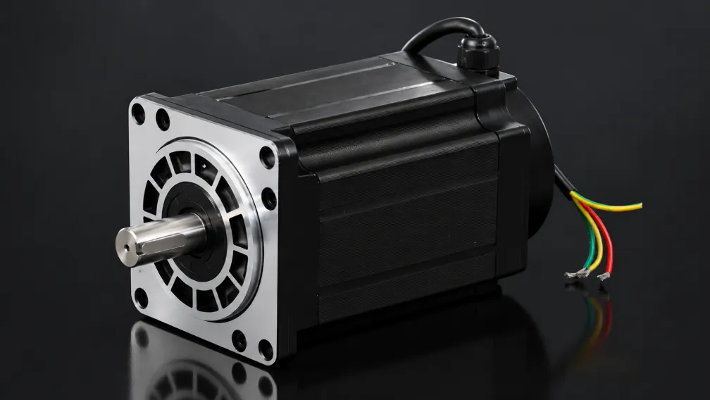
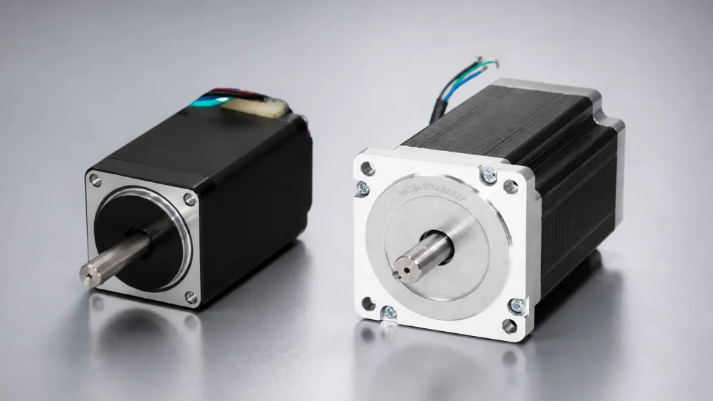
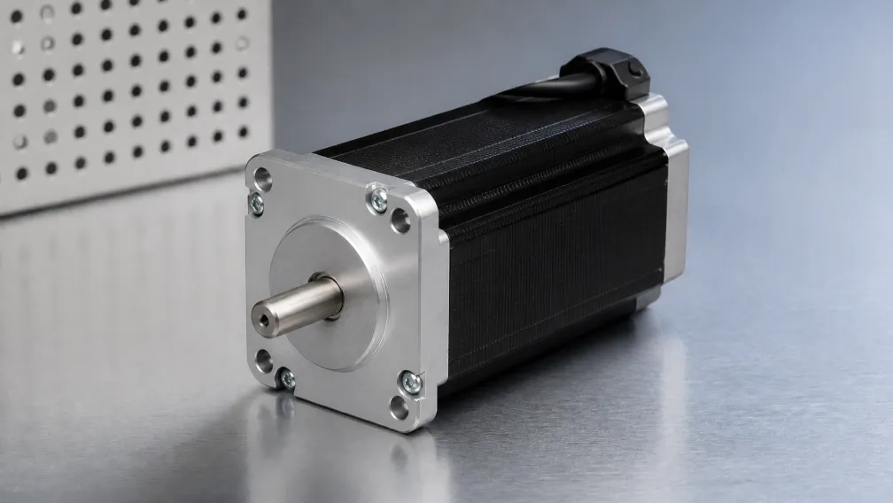
Standard industrial NEMA 23 and NEMA 34 motors are typically manufactured with Class B insulation. High-performance or harsh-environment variants utilize Class F or Class H. It is critical to understand that the "Max Winding Temperature" applies to the internal copper coils, not the external aluminum casing. The thermal gradient between the core and the outer casing is typically 15°C to 25°C. Therefore, if a Class B motor has a casing temperature measuring 105°C, the internal windings are likely nearing their critical 130°C failure point.
3. Electronic Thermal Mitigation: Drive Level Configuration
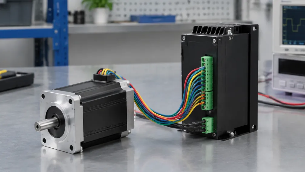
The most effective method for controlling stepper heat is configuring the motor driver to optimize current delivery based on the motion profile. Thermal management begins in the software.
Idle Current Reduction (Auto-Standby)
Virtually all modern bipolar chopper drives feature an automatic idle current reduction circuit. When the controller stops sending step pulses for a set duration (usually 0.5 to 1.0 seconds), the drive automatically cuts the holding current to 50% of the active running value. Because copper loss scales with the square of the current, reducing the current by half slashes the standstill heat generation by 75%. This is a mandatory setting for any axis that features dwell times between index moves. Be aware that holding torque also drops proportionally; confirm that the reduced holding torque is sufficient to resist gravity or static external forces on the axis.
Matching Driver Current to RMS Load
Machine builders frequently oversize motors and set the drive to maximum current "just to be safe." This guarantees maximum heat generation. The drive phase current should be set to provide the required cyclic RMS torque plus a 20% safety margin, rather than blindly defaulting to the motor's absolute maximum plate rating. Fine-tuning the current downward during the commissioning phase immediately drops the baseline operating temperature.
4. The Closed-Loop Stepper Advantage
For applications where heat generation is strictly limited—such as precision medical automation, semiconductor wafer handling, or enclosed AGV chassis—migrating to a closed loop stepper motor architecture is the ultimate thermal solution.
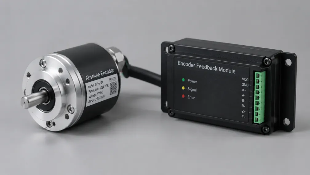
A closed-loop stepper integrates a high-resolution encoder and a specialized vector-control drive. Instead of forcing a constant current into the phases, the drive monitors the encoder feedback and applies only the precise amount of current required to execute the move and overcome the instantaneous mechanical load. At standstill with no external force applied, a closed-loop stepper draws near-zero current. This behaves identically to an AC servo system, completely eliminating the massive standstill copper losses that plague open-loop architectures. A closed-loop motor running the exact same motion profile as an open-loop motor will often operate 30°C to 40°C cooler.
5. Mechanical and Passive Cooling Strategies
When electronic mitigation is insufficient to keep temperatures within the insulation class limits, engineers must optimize the mechanical thermal dissipation path.
Front Flange Conduction: A stepper motor relies heavily on conductive heat transfer through its front mounting face. A NEMA 34 motor bolted directly to a massive, unpainted aluminum machine frame will dissipate up to 50% of its internal heat into that frame. Conversely, mounting a motor on standoffs, employing plastic thermal isolators, or bolting it to thin sheet metal eliminates this primary cooling path, forcing all heat to dissipate via convection from the casing.
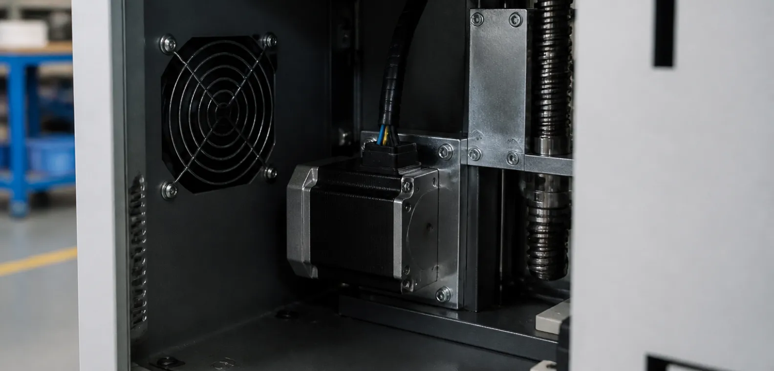
Forced Air Convection: For axes operating near maximum continuous power, passive convection in stagnant air is often inadequate. Adding a small, dedicated axial fan directed over the motor casing drastically reduces the thermal boundary layer, frequently dropping case temperatures by 15°C to 20°C. For enclosed cabinets, guarantee adequate airflow paths to extract the heated air rather than simply recirculating it.
Heatsinks: Adding extruded aluminum heatsinks to the flat sides of a square NEMA motor increases the surface area available for convective cooling. Use high-quality thermal paste or thermal interface pads between the motor casing and the heatsink to ensure efficient thermal transfer.
6. Environmental and Cabinet Constraints
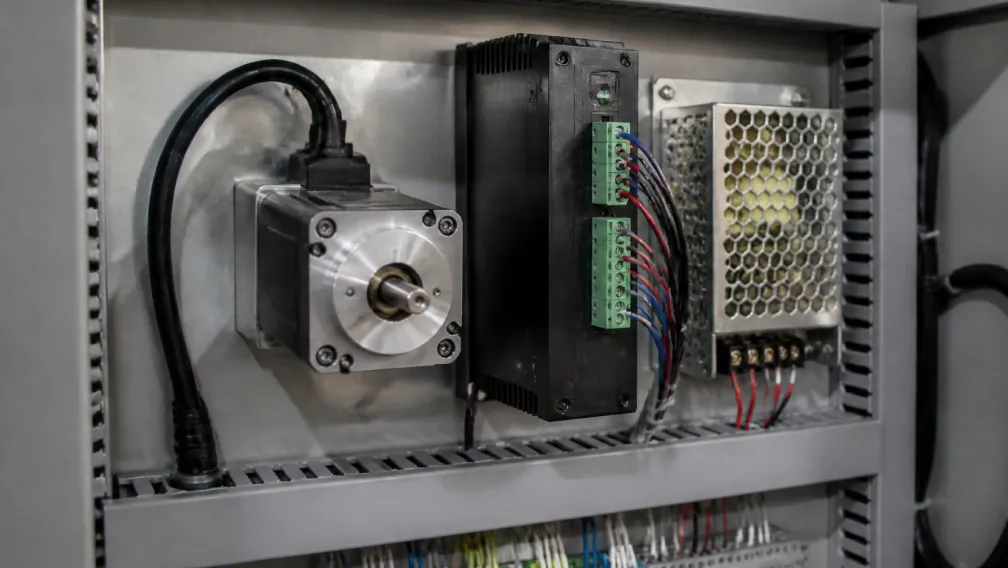
Ambient temperature directly deducts from the motor's allowable temperature rise. If a Class B motor (130°C limit) operates in a standard 20°C factory, it has 110°C of thermal headroom. If that same motor is mounted inside a sealed, unventilated automation cabinet where the trapped air reaches 55°C, its thermal headroom is cut to 75°C. In high-ambient environments, engineers must mathematically derate the continuous torque output of the motor or specify Class H insulation to survive the baseline temperatures.
Additionally, high IP-rated motors (e.g., IP65 washdown steppers) are entirely sealed. This prevents dust and liquid ingress but also traps heat. Totally Enclosed Non-Ventilated (TENV) motors lack internal air circulation, meaning heat must conduct entirely through the solid stator iron to the casing. Sealed motors require stricter adherence to duty cycle limits and current optimization.
7. OEM Thermal Validation Checklist
During the prototyping and commissioning phase of new machinery, execute the following thermal validation sequence:
- Run the machine at maximum production speed with the heaviest payload for a minimum of three hours to reach thermal equilibrium.
- Use a calibrated infrared thermometer or K-type thermocouple attached to the center of the motor casing. Do not measure near the front flange, as the mounting bracket acts as a heat sink and will read artificially low.
- Verify that the peak casing temperature remains at least 20°C below the motor's rated insulation class limit.
- Confirm that the driver's idle current reduction is active and that the motor physically cools during machine dwell states.
- If utilizing a closed-loop system, use the drive's software oscilloscope to monitor RMS current during the cycle to ensure the motor is not fighting unmapped mechanical binding.
For engineering assistance with duty cycle calculations, thermal profiling, or selecting the correct insulation class for your environment, contact the Cymotorix technical team via the application engineering page.
Frequently Asked Questions (FAQ)
Question: Is it normal for a stepper motor to be too hot to touch?
Answer: Yes. Human pain threshold is approximately 60°C. A standard industrial stepper motor can safely operate with a surface temperature of 80°C to 90°C. Rely on temperature probes rather than touch to determine if a motor is operating safely.
Question: Why does my motor get hot even when the machine is paused?
Answer: Open-loop stepper systems draw maximum current at standstill to maintain holding torque. If your driver does not have an automatic idle current reduction feature enabled, the motor will dissipate maximum I²R copper losses continuously.
Question: How does closed-loop control reduce motor heating?
Answer: Closed-loop drives use encoder feedback to apply only the exact current required for the instantaneous load. At standstill with no external load, current drops to near zero, effectively eliminating standstill heat generation.
Question: Can I cool a stepper motor with compressed air?
Answer: While effective for thermal dissipation, directing compressed air at standard IP40 stepper motors can force conductive dust, moisture, and oil directly into the motor bearings and encoder housing. Use low-pressure axial fans instead.
Question: What is the difference between Class B and Class F insulation?
Answer: Class B insulation is rated for a maximum internal winding temperature of 130°C. Class F insulation utilizes high-temperature varnishes and materials to survive up to 155°C, providing a larger thermal safety margin for heavy-duty applications.
Question: Does running at high microstepping resolutions increase motor heat?
Answer: No. Microstepping changes how the current is proportioned between phases (creating a sine wave), but it does not increase the total RMS current or the resulting I²R copper losses. Heat generation is driven by load, speed, and configured current limits.
-

Cymotorix
Stepper Motor & Servo Motor Manufacture
Cymotorix is a China-based motor manufacturer with 20+ years of experience producing hybrid stepper motors, AC servo motors, and matched drivers for OEM customers worldwide.