
Motion Control in Battery-Powered Logistics
Automated Guided Vehicles (AGVs) and Autonomous Mobile Robots (AMRs) operate under strict electromechanical constraints. Unlike stationary industrial machinery tied to a constant AC mains supply, mobile robots rely entirely on onboard DC batteries. Every actuator on the vehicle must maximize torque density, minimize physical footprint, and operate at high electrical efficiency to extend operational shifts. The engineering decisions made regarding traction, steering, and auxiliary lifting mechanisms directly dictate the payload capacity, navigational accuracy, and thermal survivability of the mobile platform.
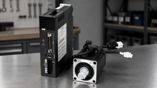
Designing the drive architecture for mobile robotics requires shifting from standard high-voltage industrial parameters to specialized low-voltage, high-current environments. This technical solution guide details how to specify, calculate, and integrate low voltage servo motors, planetary gearboxes, and stepper motors into AGV and AMR chassis for reliable autonomous logistics.
Motor Selection by AGV/AMR Function
A mobile robot typically splits its motion control into three distinct categories: traction (propulsion), steering (direction control), and auxiliary handling (lifting or conveying). Each function exerts different load profiles on the motors.
1. Traction and Main Drive Systems
The traction motors propel the entire mass of the vehicle plus its payload. These motors face severe load variations, ranging from low-resistance rolling on smooth concrete to high-torque demands when climbing ramps or overcoming floor debris.
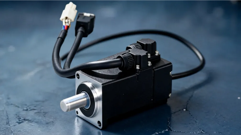
Differential drive robots utilize two independent traction wheels. Steering is achieved by varying the velocity between the left and right wheels. This configuration requires matched pairs of highly responsive servo motors to prevent drift and ensure accurate odometry feedback to the navigation system. Omnidirectional robots using Mecanum wheels require four independent traction motors, demanding tight synchronization over an industrial fieldbus to execute diagonal or lateral movements.
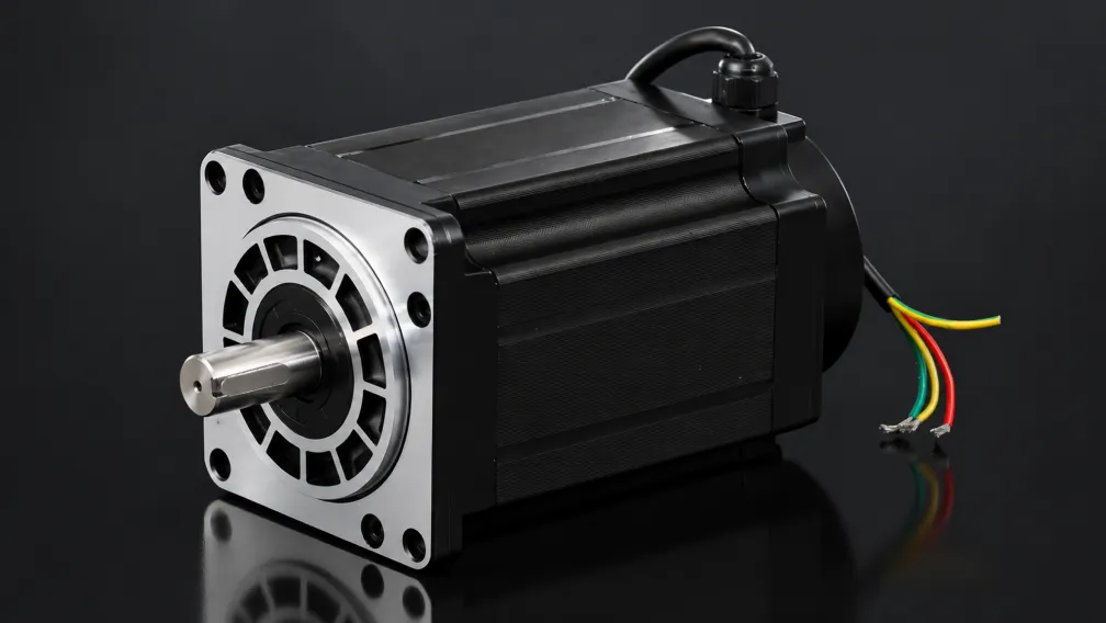
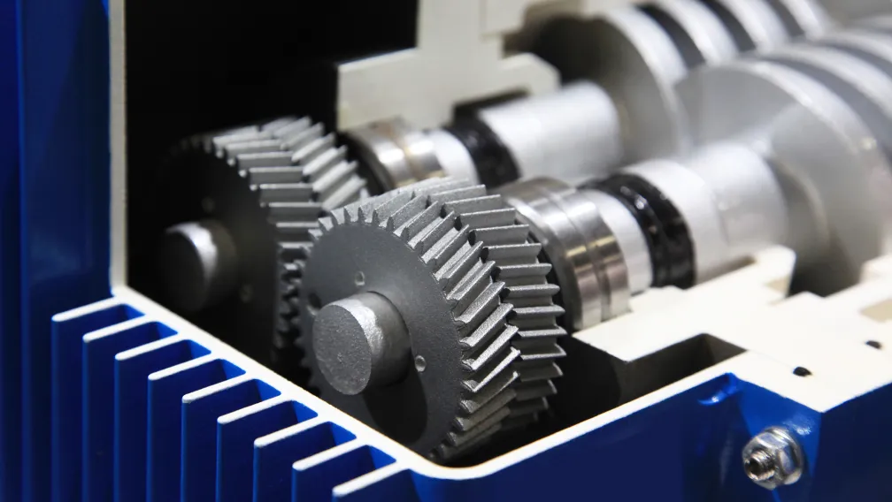
Because AGVs operate near human personnel, acceleration and deceleration profiles must be strictly controlled. Traction motors are almost universally paired with low-backlash planetary gearboxes (ratios typically between 10:1 and 30:1) to multiply torque and optimize the inertia ratio. A standard indoor logistics AMR with a 500 kg payload usually employs two 400W to 750W low-voltage servos for main propulsion.
2. Steering Mechanisms
For tricycle-drive or custom multi-steer AGVs, dedicated steering motors physically rotate the traction wheel assembly. Steering axes experience high static friction when the vehicle is stationary and require rapid torque deployment.
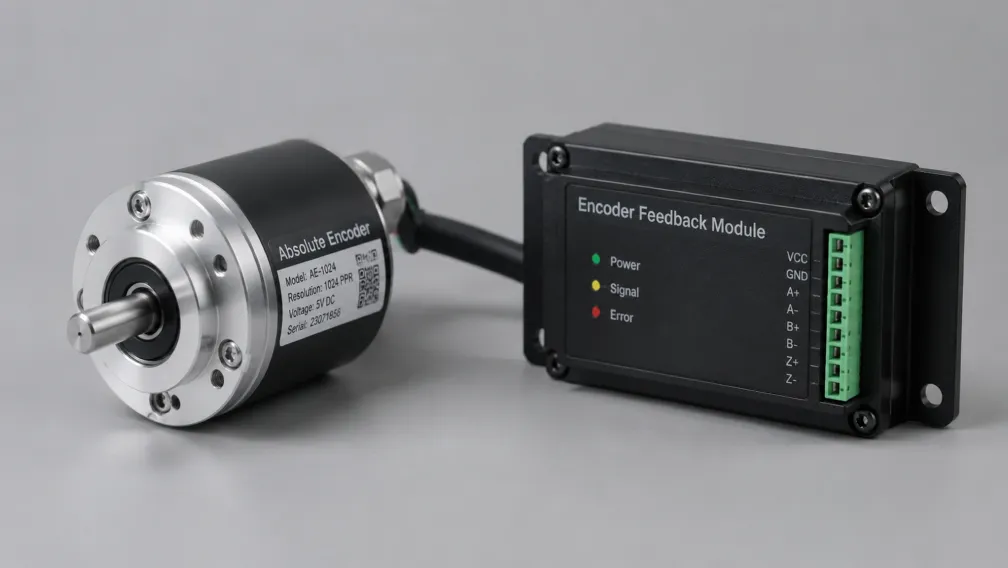
The critical requirement for a steering axis is absolute position feedback. If a robot loses power, it must immediately know the exact angle of its steering wheels upon rebooting without executing a homing sequence, which could cause a collision in a tight aisle. Consequently, steering axes mandate servo motors equipped with multi-turn absolute encoders. Because rotation speeds are low but torque demands are high, smaller frame servos coupled with high-ratio gearboxes or harmonic drives are the standard engineering solution.
3. Lifting, Jacking, and Payload Handling
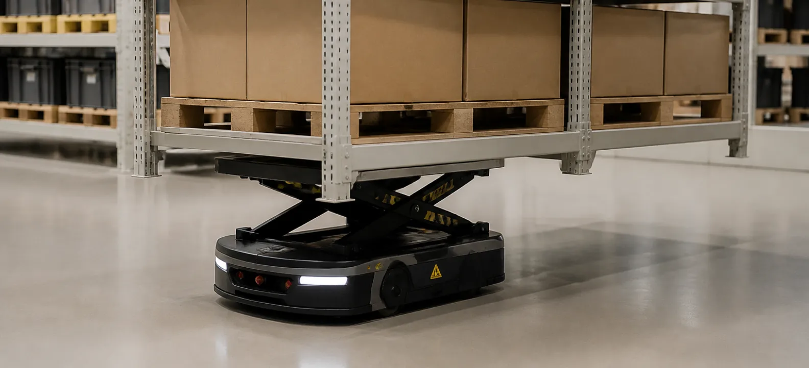
Many AMRs navigate beneath a payload cart and elevate a jacking mechanism to lift the load off the ground. The lifting axis requires immense torque at zero speed to hold the payload securely during transit. This axis is highly active during pickup and drop-off but remains entirely stationary during travel.
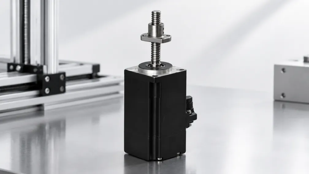
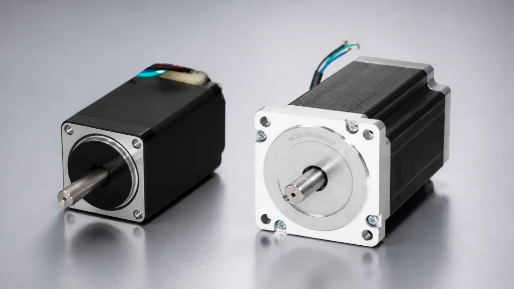
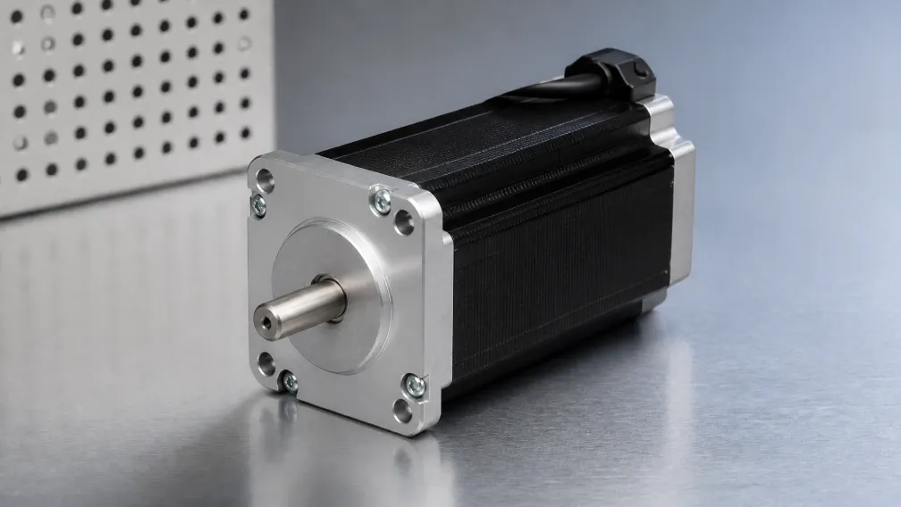
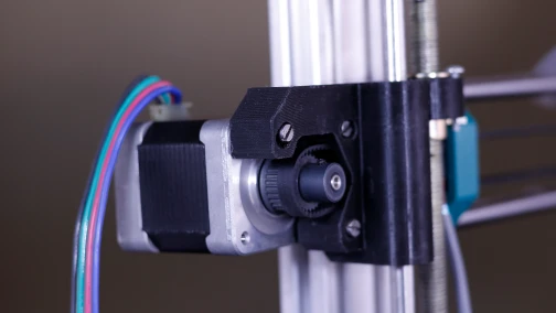
To prevent continuous battery drain, the lifting actuator must incorporate a fail-safe mechanical holding brake. While servos are used for high-speed lifts, closed loop stepper motors are highly effective for jacking mechanisms. A closed-loop stepper provides massive low-speed holding torque and utilizes a built-in holding brake to lock the load mechanically, allowing the drive to cut phase current entirely during transport, saving battery life.
Traction Motor Sizing and Physics
Sizing an AGV traction motor requires calculating the exact physical forces opposing the vehicle. Relying on simple horsepower estimations leads to stalled robots on inclines or overheated motors during continuous shifts. The total required traction force (F_total) is the sum of three components: rolling resistance, grade resistance, and acceleration force.
1. Rolling Resistance (F_roll): F_roll = μ × m × g, where μ is the coefficient of rolling friction (typically 0.02 to 0.05 for polyurethane wheels on concrete), m is the total mass (vehicle + payload), and g is gravity (9.81 m/s²).
2. Grade Resistance (F_grade): If the AGV must climb a ramp, F_grade = m × g × sin(θ), where θ is the angle of the incline. This force often represents the highest continuous torque demand on the motor.
3. Acceleration Force (F_accel): F_accel = m × a, where 'a' is the required linear acceleration (m/s²).
Once F_total is established for the worst-case scenario (accelerating up an incline), the required wheel torque (T_wheel) is calculated as: T_wheel = F_total × r, where 'r' is the radius of the drive wheel. Finally, the required motor torque (T_motor) is: T_motor = T_wheel / (Gear_Ratio × Gearbox_Efficiency).
The continuous RMS rating of the selected motor must exceed the torque required for steady-state flat travel, while the motor's peak torque rating must safely accommodate the combined acceleration and incline torque.
Voltage Constraints and Battery Architecture
Industrial AGVs typically operate on 24V or 48V DC battery architectures. This low-voltage requirement fundamentally changes motor winding design. To generate the same mechanical power as a 400V AC servo, a 48V DC servo must draw nearly ten times the current. This necessitates thick copper windings to minimize I²R copper losses and specialized motor drivers capable of handling continuous high amperage without thermal failure.
When designing the electrical architecture, engineers must account for battery voltage sag. A nominal 48V lithium-ion pack may drop to 42V under heavy acceleration loads. The motor and drive must be specified to deliver the required peak RPM and torque at the lowest expected bus voltage, preventing unexpected stalling when the battery is partially discharged.
Kinetic Energy and Regenerative Braking
When a heavily loaded AGV decelerates, its kinetic energy reverses the role of the traction motors, turning them into generators. This regenerative energy is pumped backward through the servo drive and into the DC bus.
If the battery management system (BMS) cannot absorb this sudden influx of current, the DC bus voltage will spike rapidly. If the voltage exceeds the drive's hardware limit, the drive will trigger an overvoltage fault, disabling the active magnetic braking and causing the AGV to free-roll—a catastrophic safety failure. AGV drives must incorporate active overvoltage protection and external braking resistors (chopper circuits) to burn off excess regenerative energy as heat when the battery cannot accept the charge.
Safety Systems: Safe Torque Off (STO)
Mobile robots share workspace with humans, making functional safety the highest priority. All traction and steering motor drives must feature hardware-based Safe Torque Off (STO) inputs, certified to SIL3 / PLe standards.
When a safety laser scanner detects a human in the AGV's collision path, the safety PLC drops the STO signal. The drive immediately hardware-disconnects the power semiconductors from the motor phases, ensuring no torque can be generated, regardless of software commands. Crucially, STO does not apply the mechanical holding brake; the control system must sequence the mechanical brake engagement immediately after or alongside the STO trigger to stop the vehicle's momentum.
Thermal Management in Sealed Chassis
Mobile robots are densely packed and frequently sealed to IP54 or IP65 standards to prevent dust and liquid ingress. This eliminates airflow, trapping motor and driver heat inside the chassis. The lack of convective cooling means heat must dissipate via conduction through the robot's frame.
To ensure survivability, engineers must mount traction motors and servo drives directly to heavy structural aluminum members using thermal interface materials. Additionally, the continuous current rating of the motors should be derated by 20% to 30% to account for the elevated ambient temperatures inside the sealed chassis during continuous 24/7 warehouse operation.
OEM Partnership for Mobile Robotics
Cymotorix partners with AGV and AMR manufacturers to supply engineered motion control packages tailored for low-voltage, high-reliability logistics. Our portfolio includes specialized 24V/48V servo motors, integrated drive-wheel modules, and robust absolute encoders designed to survive heavy shock and vibration environments.
Send your vehicle mass parameters, wheel diameters, speed profiles, and battery specifications to our engineering team through the application engineering contact page. We will provide detailed traction calculations, gear ratio optimizations, and thermal validation data to standardize your mobile robot's drivetrain.
Frequently Asked Questions (FAQ)
Question: Why do AGVs use 24V or 48V DC instead of higher voltages?
Answer: Lower voltages comply with Safe Extra Low Voltage (SELV) regulations, eliminating severe electrical shock hazards for operators and maintenance personnel. It also simplifies battery pack construction and management for mobile platforms.
Question: Can I use open-loop stepper motors for AGV traction?
Answer: No. Open-loop steppers draw maximum continuous current at all times, rapidly draining the battery. They also lack position feedback, meaning a skipped step causes permanent odometry and navigation errors. Use low-voltage servos or closed-loop steppers.
Question: How do you size a traction motor for a ramp or incline?
Answer: Calculate the grade resistance force (Mass × Gravity × sin(Angle)). Convert this force to wheel torque by multiplying it by the wheel radius. The motor's peak torque (factoring in the gear ratio and efficiency) must comfortably exceed this value at the required climbing speed.
Question: What is STO and why is it required on mobile robots?
Answer: Safe Torque Off (STO) is a hardware-level safety function that physically prevents the drive from generating torque-producing current. It is legally required to guarantee the robot cannot move unexpectedly during an emergency stop or human intrusion.
Question: How does regenerative braking affect the AGV battery?
Answer: Deceleration forces the motors to act as generators, pushing current back into the battery. While this can extend battery life, rapid stops with heavy payloads can cause voltage spikes. A braking resistor must be installed to burn off energy the battery cannot safely absorb.
Question: What is the best motor type for an AMR lifting mechanism?
Answer: A closed-loop stepper motor with a power-off holding brake is highly effective. It provides immense low-speed torque for jacking, and the mechanical brake holds the payload securely during transit, allowing the motor to power down and conserve battery life.
-

Cymotorix
Stepper Motor & Servo Motor Manufacture
Cymotorix is a China-based motor manufacturer with 20+ years of experience producing hybrid stepper motors, AC servo motors, and matched drivers for OEM customers worldwide.